Pepperl+Fuchs ENA TL IO Series Manual Download Page 41

 2

0

2

0

-0

9

38

ENA**TL-**IO**

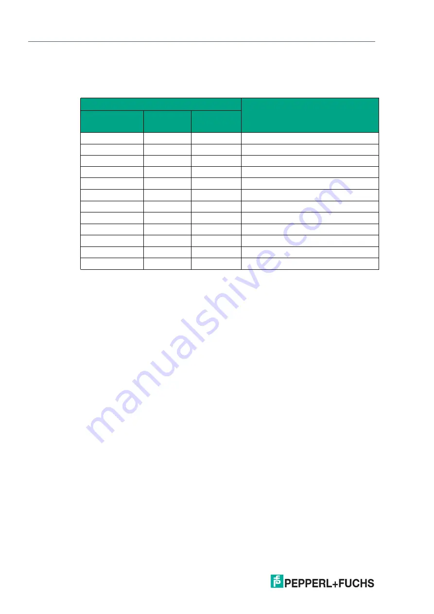
Switching Signal Characteristics

The following table shows the respective switching characteristics for each combination. It is 
necessaryto distinguish between the position sector (see previous figure) that is changed to 
the next position sector and the status of the switching channel has shortly before the sector 
change.

If the position sector is changed from sector 4 (SP1 hysteresis area) to sector 3 (= inner win-
dow area) and the SSC1 switching channel is about to switch to "high," SSC1 will switch its 
contents to "low" if sector 4 exceeds sector 3.

You can set the desired measuring range as "high active" or "low active" using the "SSC1 Con-
fig Logic" (0x41 Sub 1) parameter.

These switching characteristics apply to the singlepoint mode if the "SSC 1 Config Mode" 
(0x41 Sub 2) parameter is set to "Single point."

The general rule is

If the SPn-Hyst is larger than the "Config Position Overflow" parameter for an increasing mea-
sured value (Position), the switch point is at the position "Config Position Overflow." 

MDC1 

 Position

Switching Characteristics of SSC1 
Switching Signal 1

From "Position 
Sector"

SSC1 Value

To "Position 
Sector"

1

high

2

high 

> high

2

high

3

high 

> low

2

low

3

low 

> low

3

low

4

low 

> low

4

low

1

low 

> high

4

high

1

high 

> high

1

high

4

high 

> high

4

high

3

high 

> low

4

low

3

low 

> low

3

low

2

low 

> low

2

low

1

low 

> high

2

high

1

high 

> high

Table 7.2

Summary of Contents for ENA TL IO Series

Page 1: ...ENA TL IO Absolute Rotary Encoder with IO Link Manual...

Page 2: ...ion as well as the supplementary clause Expanded reservation of proprietor ship Worldwide Pepperl Fuchs Group Lilienthalstr 200 68307 Mannheim Germany Phone 49 621 776 0 E mail info de pepperl fuchs c...

Page 3: ...ion 12 3 3 Electrical Connection 12 4 Commissioning 14 4 1 Commissioning with IO Link on a Control Panel Online Parameterization 14 4 2 Commissioning with IO Link via FTD Framework Program Offline Par...

Page 4: ...verflow 30 6 11 DSC1 1 Param Temperature High Limit 31 6 12 DSC1 2 Param Temperature Low Limit 31 6 13 DSC1 Config Temperature Logic 31 6 14 DSC1 Config Temperature Mode 32 6 15 DSC1 Config Temperatur...

Page 5: ...EU type examination certificate EU declaration of conformity Attestation of conformity Certificates Control drawings Instruction manual Other documents 1 2 Target Group Personnel Responsibility for pl...

Page 6: ...rotation temperature and position values etc This information is transmitted as process data via IO Link to an IO Link master and further to a higher control level Connect the rotary encoder to an IO...

Page 7: ...r to carry out modifications and or repairs and doing so will void the warranty and exclude the manufacturer from any liability In the event of any serious errors stop using the device Secure the devi...

Page 8: ...gy The internationally standardized interface provides value at all stages from plant design and installation through to operation and maintenance This value is achieved by sustained cost reductions a...

Page 9: ...ters for the IO Link devices read and monitor the status and diagnostic data IO Link data is integrated into an application program using function blocks 2 2 LED Indicators The device has a green yell...

Page 10: ...levant ENA TL IO at www pepperl fuchs com IO Link Master02 USB USB to IO Link adapter box for controlling an IO Link sensor directly via a PC V1 G 0 6M PUR V1 G Cordset M12 to M12 4 pin PUR cable for...

Page 11: ...d statuses This presents a significant risk of personal injury and property damage Warning Check electrical connections before switching on the plant Check all electrical connections before switching...

Page 12: ...precision instrument Rotary encoders from Pepperl Fuchs are rugged however they should nevertheless be protected against damage in ambient conditions by taking appropriate protective mea sures In part...

Page 13: ...USB Caution No voltage permitted at Pin 2 The ENAxxTL IO product group does not support functionality for Pin 2 in terms of a digital input output However there is a real physical connection to the PC...

Page 14: ...levant ENA TL IO absolute rotary encoder online at www pepperl fuchs com or use the IODDfinder at https iodfinder io link com For offline parameterization IO Link devices are already configured before...

Page 15: ...e package is installed on your computer 2 Connect the absolute rotary encoder to an IO Link master via a suitable M12 cordset 3 Connect the IO Link master to a USB connection on your PC via a USB cabl...

Page 16: ...er 16 bits 16 1 MV1_S calemax Reserved 6 bits 10 0 Low DSC1 2 Tempera ture Warning 2 Diagnosis Signal Channel 1 2 Tem perature Warning 1 Boolean 1 bit 9 0 Low 1 High DSC1 1 Tempera ture Warning 1 Diag...

Page 17: ...left and 12 000 on the right The physical shaft position is the same on the left and right see shaft However the MDC1 Position process data show different data on the left and right This is explained...

Page 18: ...as required Refer to information on the Config ST Resolution and Position Value Overflow parame ters 5 3 MDC1 ST Resolution Measurement Data Channel 1 Singleturn Resolution The MDC1 ST Resolution pro...

Page 19: ...nding multiturn position number of full revolutions completed If a complete rev olution means 1000 steps a measured value equating to MDC1 Position 1875 means that one full revolution and a further 87...

Page 20: ...osition remainder measuring steps per revolution 0 by definition Taking the sample numbers from above the result is Singleturn resolution Config ST Resolution MDC1 ST Resolution number of mea suring s...

Page 21: ...ing and the current direction of rotation 5 7 MDC2 Auxiliary Measurement Measurement Data Channel 2 Auxiliary Measurement The MDC2 Auxiliary Measurement process data content describes another availabl...

Page 22: ...SC1 1 Param Temperature High Limit DSC1 Config Temperature Mode DSC1 Config Temperature Logic DSC1 Config Temperature Hyst 5 10 DSC1 2 Temperature Warning 2 Diagnosis Signal Channel1 2 Temperature War...

Page 23: ...me on the left and right see shaft However the MDC1 Position process data show different data on the left and right This is explained by the division of a full revolution into 1000 steps in one case a...

Page 24: ...mation on the MDC1 ST Resolution process data content and the Config Position Overflow parameter 6 2 SSC1 Param SP1 Switching Signal Channel 1 Parameter Setpoint 1 The SSC1 Param SP1 parameter is used...

Page 25: ...below uses an example to illustrate the relationship between SP1 and SP2 Figure 6 3 The general rule for switch points SP1 and SP2 is that switch points SP1 and SP2 can be set independently of each o...

Page 26: ...meter is used to set the evaluation mode for the signal evalua tion The resulting switching signal depends on values selected for SP1 and SP2 for Logic and Mode Set one of the following modes Deactiva...

Page 27: ...vated Mode Figure 6 5 Single Point Mode as High Active Signal Figure 6 6 Window Mode as High Active Signal Figure 6 7 Two Point Mode as High Active Signal Figure 6 8 SP max SSC SP min SP 2 SP 1 inacti...

Page 28: ...s on the mode selected in the SSC1 Config Mode parameter It is effective for the Single Point and Window modes only The effect in each mode is shown in the figures below Single Point Mode with Hystere...

Page 29: ...Red section area between setpoint 1 and setpoint 2 Position sector 4 Yellow section hysteresis area of the larger setpoint P o s i t i o n s e c t o r 1 Position sector 4 P o s i t i o n s e c t o r 3...

Page 30: ...witching characteristics apply to the singlepoint mode if the SSC 1 Config Mode 0x41 Sub 2 parameter is set to Single point 6 7 Config Auxiliary Measurement Configuration Auxiliary Measurement The Con...

Page 31: ...offset the zero crossing This value can be used to redefine a suitable zero crossing during operation or for a particular installation situation Even after switching the rotary encoder off and on aga...

Page 32: ...lutions are possible The third revolution is counted upward by a further 1 4 Once the overflow value has been exceeded the position value begins counting again from zero A Mathematical Generalization...

Page 33: ...ature High Limit The DSC1 1 Param Temperature High Limit parameter is used to set the upper temperature limit value and corresponds to the switching threshold of the DSC1 1 Temperature Warning 1 switc...

Page 34: ...rature Hyst parameter is used to set the required delayed effect of the DSC1 1 Param Temperature High Limit and DSC1 2 Param Temperature Low Limit signal bits despite a real change in the temperature...

Page 35: ...Parameterization Hysteresis in High and Low Limit Active mode as active high signal Figure 6 15 Temp max Temp min Temp low limit Temp high limit DSC1 2 Temp Warning 2 DSC1 1 Temp Warning 1 inactive a...

Page 36: ...g limit The colored value range between the lower and upper switching limit is known as the window range SP1 setpoint 1 and SP2 setpoint 2 can be configured with the same assigned value and loaded int...

Page 37: ...Figure 7 2 Switching characteristics with overflow function In this example the selected SP1 of 1950 is higher than the Position Overflow set at 1850 The SSC1 Switching Signal Channel 1 process data c...

Page 38: ...ing on the current direction of rotation and the current status of the switching channel there is either a change or no change in the switch ing channel if the limits are exceeded The following table...

Page 39: ...with SP1 and SP2 Larger than Overflow You can set a uniform hysteresis area for each of the switch points SP1 Setpoint 1 and SP2 Setpoint 2 Keep in mind that the window mode hysteresis limit has an ou...

Page 40: ...ere using dashed lines Position sector 1 White section area outside the hysteresis areas and the setpoints Position sector 2 Yellow section hysteresis area of the smaller setpoint Position sector 3 Re...

Page 41: ...et the desired measuring range as high active or low active using the SSC1 Con fig Logic 0x41 Sub 1 parameter These switching characteristics apply to the singlepoint mode if the SSC 1 Config Mode 0x4...

Page 42: ...Switch on the voltage supply The plug on the connection cable is not correctly con nected to the device plug on the rotary encoder Connect the plug to the sensor and tighten the union nut by hand Wir...

Page 43: ...2020 09 40 ENA TL IO Repair and Servicing 9 Repair and Servicing The device must not be repaired changed or manipulated In case of failure always replace the device with an original device...

Page 44: ...Pepperl Fuchs Quality Download our latest policy here www pepperl fuchs com quality www pepperl fuchs com Pepperl Fuchs Subject to modifications Printed in Germany DOCT 6723...

Reviews: