PENNCO 15B SERIES Installation, Operation & Maintenance Manual Download Page 6

6

VENTILATION & COMBUSTION AIR

COMBUSTION AIR REQUIREMENTS

(Minimum Square Inches Requirement)

Model 

No.

Unconfined Area*

Confined Area**

Inside 

Combustion Air

Outside 

Combustion Air 

Outside Combustion Air

 1 Sq. In./1000 

Btu/Hr. 

(Fig. #3)

1 Sq. In./5000 

Btu/Hr. 

(Fig. #4)

Vertical Ducts 

1 Sq. In./4000 

BTU/Hr.

Horizontal Ducts 

1 Sq. In./2000 

BTU/Hr.

15B045

100

10

13

25

15B070

100

15

19

38

15B096

100

20

25

50

15B120

125

25

32

63

15B145

150

30

38

75

15B175

175

35

44

88

15B195

200

40

50

100

15B245

250

50

63

125

15B295

300

60

75

150

* A space whose volume is not less than 50 cubic feet per 1000 BTU per hour of all 

appliances installed in that space (cubic feet of space = height x width x length)

** A space whose volume is less than 50 cubic feet per 1000 BTU per hour of all 

appliances installed in that space (cubic feet of space = height x width x length)

Air  openings  to  combustion  area  must  not  be  obstructed.  By  following  the  instructions  below, 
adequate combustion air can be maintained.

WARNING

!


Ventilation of the boiler room must be adequate to provide 

1. 

sufficient air to properly support combustion per the latest 

revision of the National Fuel Gas Code, ANSI Z223.1.
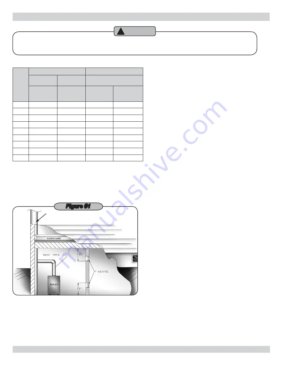
Figure #1

CHIMNEY OR

TYPE B VENT PIPE

When a boiler is located in an unconfined space in a 

2. 

building or conventional construction frame, masonry or 

metal building, infiltration normally is adequate to provide 

air for combustion and ventilation. However, if the equip

-

ment is located in a building of tight construction (See the 

National Fuel Gas Code, ANSI Z223.1 latest revision), the 

boiler area should be considered as a confined space. 

In this case air for combustion and ventilation shall be 

provided according to Step 5. If there is any doubt, install 

air supply provisions in accordance with the latest revision 
of the National Fuel Gas Code.

When a boiler is installed in an unconfined space in a 

3. 

building of tight construction, air for combustion and ven

-

tilation must be obtained from outdoors or from spaces 

freely communicating with the outdoors. A permanent 
opening or openings having a total free area of not less 
than 1 square inch per 5000 Btu per hour of total input 

rating of all appliances shall be provided. Ducts may be 

used to convey makeup air from the outdoors and shall 
have the same cross-sectional area of the openings to 
which they are connected.

When air for combustion and ventilation is from inside 

4. 

buildings, the confined space shall be provided with two 

permanent openings, one starting 12 inches from the 

top and one 12 inches from the bottom of the enclosed 

space. Each opening shall have a minimum free area 
of 1 square inch per 1000 Btu per hour of the total input 

rating of all appliances in the enclosed space, but must 

not be less than 100 square inches. These openings must 

freely communicate directly with other spaces of sufficient 

volume so that the combined volume of all spaces meets 

the criteria for an unconfined space. (Figure #1)

When the boiler is installed in a confined space and all air 

5. 

is provided from the outdoors the confined space shall be 

provided with one or two permanent openings according 

to methods A or B. When ducts are used, they shall be 

of the same cross sectional area as the free area of the 
area of the openings to which they connect. The minimum 

dimension of rectangular air ducts shall be not less than 3 

x 3 inches or 9 square inches.

When installing two openings, one must commence with-

A. 

in 12 inches from the top and the other within 12 inches 

from the bottom of the enclosure. The openings shall 

communicate directly, or by ducts, with the outdoors or 

spaces (crawl or attic) that freely communicate with the 

outdoors. One of the following methods must be used to 

provide adequate air for ventilation and combustion.

Summary of Contents for 15B SERIES

Page 1: ...kirk NY 14048 www ecrinternational com R An ISO 9001 2000 Certified Company 15B SERIES Cast Iron Gas Fired Boilers For Forced Hot Water INSTALLATION OPERATION MAINTENANCE MANUAL MODEL NUMBERS 15B045 1...

Page 2: ......

Page 3: ...or elimination of fac tory equipped supplied or specified components may result in property damage personal injury or the loss of life 4 TO THE OWNER Installation and service of this boiler must be p...

Page 4: ...rs 3 Tank sized for non ferrous baseboard or radiant panel systems Increase size for cast iron baseboard and radiation Net I B R ratings include 15 allowance for normal piping and pick up load Manufac...

Page 5: ...lighting and other performance 4 criteria with the gas manifold and control assembly on the boiler per the latest revision of ANSI Z21 13 CGA 4 9 The boiler shall be installed such that the gas ignit...

Page 6: ...National Fuel Gas Code When a boiler is installed in an unconfined space in a 3 building of tight construction air for combustion and ven tilation must be obtained from outdoors or from spaces freely...

Page 7: ...nch from the back and 6 inches from the front of the boiler The opening shall directly communicate with the outdoors or shall communicate through a verti cal or horizontal duct to the outdoors or spac...

Page 8: ...ating boiler During heating cycle open valves A and B close valves C and D During cooling cycle open valves C and D close valves A and B Maintain a minimum clearance of one inch to hot water C pipes W...

Page 9: ...tion This method of piping however is not typically required for baseboard heat ing systems Typical installations where bypass piping is used are as follows This method is used to protect boilers from...

Page 10: ...ALVE HOSE BIB FLOW CONTROL VALVE EXPANSION TANK BOILER DHW CIRCULATOR CH CIRCULATOR PRIORITY ZONE CIRCULATOR EXPANSION TANK WATER INLET FLOW CONTROL VAVLE SHUT OFF VALVE PRESSURE REDUCER VALVE CHECK V...

Page 11: ...RIORITY ZONE BOILER WATER INLET CH DHW SYSTEM CIRCULATOR USE FULL PORT ZONE VALVE FOR OPTIMUM TANK PERFORMANCE CONSIDER USING ZONE CIRCULATOR SEE FIGURE 5 ZONE 4 CIRCULATOR SHUT OFF VALVE PRESSURE RED...

Page 12: ...urn doors win dows exhaust fans fireplace dampers and any other gas burning appliances to their previous condition of use Any improper operation of the common venting system 7 All installations of boi...

Page 13: ...tor through bracket 3 hole on Damper Motor frame Tighten locknut onto Damper wire harness connector 4 Plug Damper connector into socket on Damper Motor 5 frame Replace Damper Motor cover and wire Damp...

Page 14: ...iping system during 4 any pressure testing of the gas piping After reconnecting leak test gas connection and boiler piping before placing boiler back into operation Natural Gas Propane Min Supply Pres...

Page 15: ...15 Wiring Diagram 24V Standing Pilot...

Page 16: ...16 Wiring Diagram 24V Intermittent Ignition...

Page 17: ...17 Wiring Diagram 24V Standing Pilot WITH LWCO...

Page 18: ...18 Wiring Diagram 24V INTERM IGNITION WITH LWCO...

Page 19: ...all your gas supplier from a neighbor s phone Follow the gas supplier s instructions If you cannot reach your gas supplier call the fire department CAUTION C Use only your hand to push in or turn the...

Page 20: ...COVER SCREW OUTLET PRESSURE TAP TAP PRESSURE INLET GAS INLET GAS OUTLET TH TR ON OFF PILOT Figure 16 NOTE Somegascontrolknobscannotbeturnedfrom PILOT to OFF unless knob is pushed in slightly DO NOT F...

Page 21: ...per and dangerous operation CAUTION Verify proper operation after service The service agency or owner should make certain the system is filled with water to minimum pressure and open air vents if used...

Page 22: ...S BURNERS Figure 20 BURNER DOOR The pilot flame should envelop to inch of the tip of the pilot thermocouple ignition sensing electrode or mercury sen sor Figure 21 IGNITION ELECTRODE 3 8 TO 1 2 IN FLA...

Page 23: ...should be changed if the final manifold pressure varies more than plus or minus 0 3 inches water column from the specified pressure Primary air adjustment is not necessary therefore air shutters are...

Page 24: ...ltimeter Gauge 4 Jacket Side Right 16 Right End Section 28 High Limit Control 5 Left End Section 17 Jacket Side Left 29 Pipe Bushing 6 Push Nipple 18 Relief Valve 30 Well 7 Jacket Top 19 Pipe Nipple 3...

Page 25: ...aight Flange NPT 175 195 245 295 LP ONLY 1 6 VG 006 00 Internal Bushing x ALL LP 1 7 356 2 1 01 Manifold 045 1 356 2 1 02 Manifold 070 096 Item Part No Description Qty 7 356 2 1 03 Manifold 120 145 1...

Page 26: ...6 1 B Center Section 120 145 2 B Center Section 175 195 3 B Center Section 245 4 B Center Section 295 6 Item Part No Description Qty 7 100 2 2 01 B Left Hand Section 1 8 43300976 Push Nipple 2 Mach 04...

Page 27: ...702 Flue Collector Restrictor 070 3461703 Flue Collector Restrictor 096 3461704 Flue Collector Restrictor 295 Item Part No Description Qty 8 34620501 Flue Collector 045 1 34620502 Flue Collector 070 0...

Page 28: ...02 Natural Gas Q345A PILOT 1 240007096 LP Q345A Pilot Included with 3 Pilot Tube Assembly Kit above CONTINUOUS PILOT Item Part No Description Qty 1 109007296 PILOT BRACKET ASSEMBLY 1 2 HW 005 01 BRACK...

Page 29: ...18 1 5 1190001 Pipe Elbow 90 1 14 37513301 Wire Rollout Spill 28 2 6 1260006 Gauge Theraltimeter 1 15 14662070 Pilot Spark Control 1 7 37519501 Harness Circulator 72 1 16 EF03601 Clamp 3600 White 2 8...

Page 30: ...ion LP to Natural 15B245 550001277 Kit Conversion LP to Natural 15B295 550001278 Kit Conversion LP to Natural NATURAL GAS TO LP Model Part No Description 15B045 550001279 Kit Conversion Natural to LP...

Page 31: ...31...

Page 32: ...85 Middle Rd Dunkirk NY 14048...

Reviews: