background image

applications for performance Upgrade and HurricaneShield: 

6" 

16" MAX  

O.C. 

16" MAX  

O.C. 

16" MAX  

O.C. 

16" MAX  

O.C. 

6" 

6" 

6" 

6" 

6" 

6" 

6" 

DOUBLE OPERABLE 

6" 

6" 

16"  

MAX.  

O.C. 

2C

6" 

6" 

16"  

MAX.  

O.C. 

2C

2C

5E

16" MAX  

O.C. 

16" MAX  

O.C. 

6" 

6" 

6" 

6" 

SINGLE FIXED OR OPERABLE 

6" 

6" 

16" 

MAX.  

O.C. 

6" 

6" 

16"  

MAX.  

O.C. 

2C

2C

2C

5E

DIAGRAM FOR 

PLACEMENT OF 

THRESHOLD SCREWS &

INSTALLATION CLIPS

C. 

Doors using Installation clips:

 Install 

installation clips. Place  each clip so 

the lip is facing up and against the 

installation fin at the locations shown 

in the placement diagram. Secure each 

clip by driving a #6 x 5/8” corrosion 

resistant screw through each of the 

outer two holes of the three holes 

shown. 

Note: If clips are to be bent; pre-bend 

before attaching to frame.

6“ from end 

Lip 

#6 x 5/8” corrosion 
resistant screws 

2C

3

SETTINg AND  

fASTENINg 

THE DOOR

A. 

place three 3/8” beads of sealant.


Place the first beads sealant ½” from 

the base of the interior sill pan lip. 

This bead should also continue up the 

corner of the sill pan at each end, sealing the vertical 

joints of the sill pan legs. Continue the first bead  up 

6” onto each jamb side of the rough opening. The 

second bead should be approximately ½” from the 

exterior edge of the rough opening, running from 

jamb to jamb with a 2” break in the middle of the 

opening. Place a third sealant bead in the groove 

of the sill support from end to end or ¼” from the 

exterior edge of the wood blocking. 

Note: Sill sealant detail is the same for applications 

with and without optional sill pan.

3A

1

2

3

6”

PERFORMANCE UPGRADE & HURRICANESHIELD DOORS

ALL

 DOORS 

 ALL

 DOORS

EXTERIOR SILL P

AN LIP 

INTERIOR SILL P

AN LIP 

2nd Bead 

Leave a 2" break  

in center of pan 

1st Bead 

3rd Bead 

3A 

6”

Out-Swing Vent or Fixed

In-Swing Vent

Out-Swing Vent or Fixed

In-Swing Vent

Out-Swing Vent and Fixed

In-Swing Vent

Screw  
Location

Screw  
Location

Applications without sill pan

Summary of Contents for 818L0100

Page 1: ...be used with any other construction method Installation instructions for use with other construction methods multiple units or bow and bay windows may be obtained from Pella Corporation a local Pella...

Page 2: ...urethane or silicone sealant 2 to 3 tubes per door Great Stuff Window and Door Insulating Foam Sealant by the Dow Chemical Company or equivalent low pressure polyurethane window and door foam DO NOT u...

Page 3: ...ashing tape and fold Cut 1 wide tabs at each corner 1 2 from each side of the corner 1F Fold tape to the exterior and press firmly to adhere it to the water resistive barrier 1F 1 1 2 1 2 6 1E 1 1G G...

Page 4: ...erior sill pan lip is flush with the exterior of the rough opening N Apply sill flashing tape Cut a piece of flashing tape 2 longer than the opening width Apply at the bottom of the opening covering t...

Page 5: ...es of flashing tape 1 1 2 x 6 and apply to the bottom corners of the opening by beginning in the corner of the sill pan with 3 4 of the tape applied to the sill pan and 3 4 of the tape applied to the...
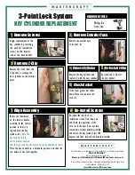
Page 6: ...the first beads sealant from the base of the interior sill pan lip This bead should also continue up the corner of the sill pan at each end sealing the vertical joints of the sill pan legs Continue t...
Page 7: ...strike location between the door and the sides of the opening Insert shims in other locations as needed starting up 6 from the bottom of the door to square it in the opening Make sure that the reveal...

Page 8: ...allation Applications Only Install sill screws Remove the threshold screws and insert a 8 x 3 stainless steel screw provided into each hole For masonry floors use a 3 16 masonry screw in place of the...

Page 9: ...es can be used to move the panel side to side by moving all hinges in the same direction or the hinges can slightly rotate the panel by adjusting the hinges in opposite directions Use a T20 Torx wrenc...

Page 10: ...hick adjust the dimension of the fold so the exterior sealant line will cover the exterior edge of the tape Exterior 4A B Apply top flashing tape Cut a piece of flashing tape long enough to go across...

Page 11: ...ent Placement Fixed Placement 5A 6 16 MAX O C 16 MAX O C 6 6 6 5A 6 16 MAX O C 16 MAX O C 6 6 6 In Swing Clearance Hole Location Clearance Hole Location Clearance Hole Location Clearance Hole Location...

Page 12: ...er x 3 and pilot drill per screw manufacturers s recommendations NOTE Not required on In swing Fixed doors Installation Clip Method F Fasten the door to the opening by driving two 8 x 1 1 4 corrosion...

Page 13: ...s and the rough opening Caution Ensure use of low pressure polyurethane window and door insulating foams and strictly follow the foam manufacturer s recommendations for application Use of high pressur...

Page 14: ...Clearance Backer Rod and Sealant typical Perimeter Sealant must extend to roomside of Accessory Groove Accessory Groove Insulating Foam 3 8 Min 3 8 Insulating Foam Perimeter Sealant must extend to ro...

Page 15: ...ce Use of inappropriate finishes solvents brickwash or cleaning chemicals will cause adverse reactions with window and door materials and voids the Limited Warranty CARE AND MAINTENANCE Care and maint...

Page 16: ...y against the weather strip Remove the strike and adjustable strike shim Remove the tabs from the adjustable strike shim and install so that the thicker side is visible at the strike edge Reinstall th...

Reviews: