Part 2- Tyre changer
Specifications
Dimensions of the external locking rim..... 10 ~ 21 ”
Dimensions of the internal locking rim ..... 12 ~ 24 ”
Max. Wheel diameter ....................... 1040mm (41 ”)
Max. Wheel width ............................... 355mm (14 ”)
Working pressure ......................................... 8-10 bar
Power supply .........110V (1ph) / 220V (1ph) / 380V
(3ph)
Optional motor power ............... 0.75 / 0.55 / 1.1 kw
Max. Rotating torque (turntable) ............... 1078 Nm
Overall Dimension ............................. 96 * 76 * 93cm
Noise level ......................................................... 75dB
The workplace
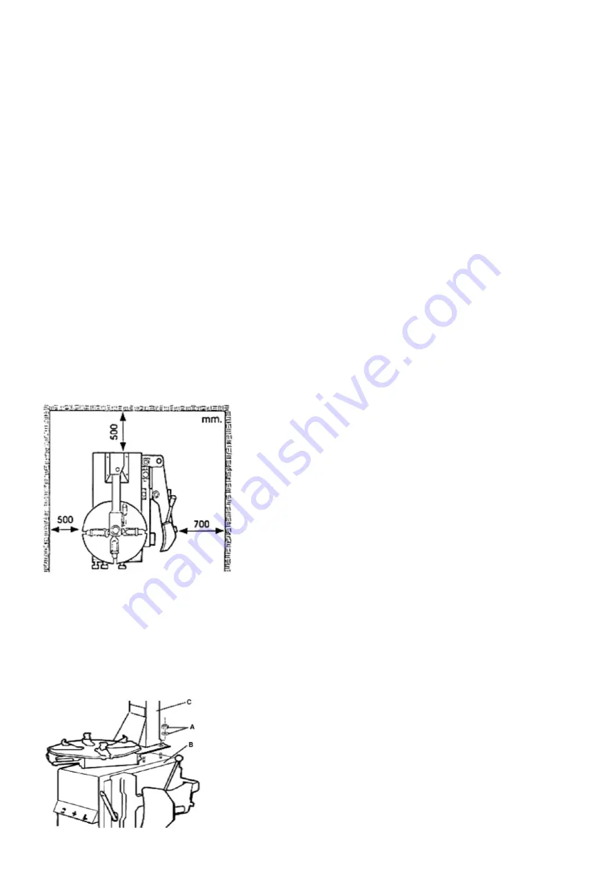
Choose a workplace in accordance with statutory
safety regulations. The machine requires a free
working surface of at least 500 mm to the nearest
wall on the left and behind and 700 mm on the right
side. Place the machine on a stable and stable
floor, use a spirit level to check that the machine
is level. Drill four holes in the floor and mount the
machine with an expander bolt and tighten.
Installation
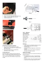
Unscrew the washers and nuts (A) from the four
mounting bolts located on the top (B) of machines.
Get help lifting the tower stand (C) and placing
it over the four mounting bolts. Secure the stand
securely using the washers and nuts.
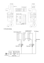
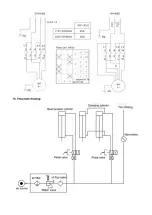
Connect to compressed air
•
Fully depress the foot control (V) so that the
clamping jaws do not open unintentionally.
•
Connect compressed air to the tire machine.
The connection hose must have an inner
diameter of at least 7-8 mm, and give a
pressure of 8 to 10 bar. The air pressure must
not exceed 10 bar, in which case adjust the
pressure regulator.
Connect to electricity
•
Before connecting to the electrical outlet, check
that the mains voltage corresponds to the rated
voltage on the type plate.
•
The machine must be connected to a grounded
electrical outlet that is secured with at least,
10A. If you are unsure, contact a qualified
electrician.
Warning!
Keep hands and body away from moving parts of
the tire machine. Do not wear necklaces, scarves
or loose clothing. Unreadable warning signs shall
be replaced immediately. Do not use the machine if
they are missing. Check that the signs are
readable for the operator.
User controls
•
The lock button (K), is used to release / lock the
mounting head on the swingarm.
•
The foot pedals for clamping jaws (V) are used
to open and close the four jaws.
•
The clincher release pedal (U) is used to
operate the clincher arm.
•
The foot pedal (Z) is used to start the
rotating table (Y), it must rotate clockwise for
the machine to tilt off the tire correctly.
Basic functions
Check that the basic functions of the machine are
correct after the installation has been completed.
Press the pedal to rotate the table clockwise. Push
the pedal up to rotate the table counterclockwise.
Press the clincher release pedal to activate the
clincher arm, release the pedal and move the arm
to the side by hand. Depress the foot pedal for the
clamping jaws completely, to open the jaws on the
table to the maximum. Press again to close the
jaws. With the pedal in the center position, the jaws
are in a stationary position.
Changing a tire involves three steps:
•
Depress the tire clamp.
•
Disassembled tire
•
Mounted tire
Summary of Contents for 498192
Page 1: ...Tyre changer balancer 2 in 1 D ckmaskin balanserare 2 i 1 Item No 498192...
Page 11: ......
Page 16: ......
Page 17: ......
Page 18: ......
Page 19: ......
Page 20: ......
Page 21: ......
Page 22: ......
Page 23: ......
Page 33: ......
Page 38: ......
Page 39: ......
Page 40: ......
Page 41: ......
Page 42: ......
Page 43: ......
Page 44: ......
Page 45: ......

