


LED display and keyboard. Speed testing and
positioning system consist of gearbox and
electronic clutch. Horizontal and vertical
pressure sensors.
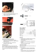
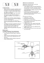
The workplace
Choose a workplace in accordance with statutory
safety regulations. The machine requires a free
working surface of at least 500 mm to the nearest
wall on the left and behind and 700 mm on the
right side. Place the machine on a stable and
stable floor, use a spirit level to check that the
machine is level. Drill four holes in the floor and
mount the machine with an expander bolt and
tighten with a fixed wrench.
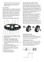
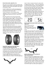
Introduction of the display control panel
1. Digital reading, amount of imbalance, inside
2. Digital reading, amount of imbalance, outside
3. Balancing mode
4. Pushbuttons, manual DISTANCE setting
5. Pushbuttons, manual WIDTH setting
6. Pushbuttons, manual DIAMETER setting
7. Show real imbalance amount (less than 5
grams), function key 1gram / ounce 2mm / inch
3-calibration
8. Push button, recalculation
9. Function key for selecting balancing mode
10. Show imbalance position outside
11. Show imbalance position on the inside
12. Push button, optimization of imbalance
13. Split function
14. Indication of optimization
15. Indication of the ALU-S mode
16. Information about division
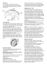
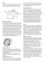
Assembly and disassembly of wheels
Before mounting the centering cone on the
machine’s balance shaft, check that the surfaces
of the centering cone and the balance shaft are
clean, no sand or dirt, and that the tire is also clean.
Remove any previous balance weights, check the
air pressure and that the rim is not damaged. Then
fit the appropriate centering cone. Mount the wheel
on the balance shaft and fasten with the quick nut.
Remember that poor centering leads to
unnecessary imbalance.
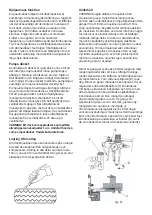
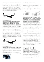
Placement of centering cone in most cases of
aluminum rims. (To protect the rim on the outside
against the quick nut). Positive positioning is
commonly used. It works easily and is useful for
different types of sheet metal rims and thin
aluminum rims. Placement of centering cone in
most cases of sheet metal rims. Negative
positioning is used to protect the inner hole of the
rim and the main axle is positioned exactly even if
the outside of the wheel is deformed. Used for all
sheet metal rims, especially thick sheet metal rims.
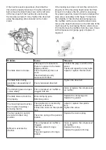
Disassembly of wheels
Release the quick nut by turning it
counterclockwise and then release it with the red
levers. Remove the cone and lift the wheel, being
careful not to scratch the balance shaft.
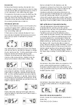
Programming of rim data
(done in different ways depending on the mode)
Switch on the main power - the machine starts up
automatically and is ready after 2 seconds. The
machine automatically adjusts position and is
ready for input data about the rim.
Summary of Contents for 498192
Page 1: ...Tyre changer balancer 2 in 1 D ckmaskin balanserare 2 i 1 Item No 498192...
Page 11: ......
Page 16: ......
Page 17: ......
Page 18: ......
Page 19: ......
Page 20: ......
Page 21: ......
Page 22: ......
Page 23: ......
Page 33: ......
Page 38: ......
Page 39: ......
Page 40: ......
Page 41: ......
Page 42: ......
Page 43: ......
Page 44: ......
Page 45: ......


