background image


MPEG-4 DVR 

45

SETUP 

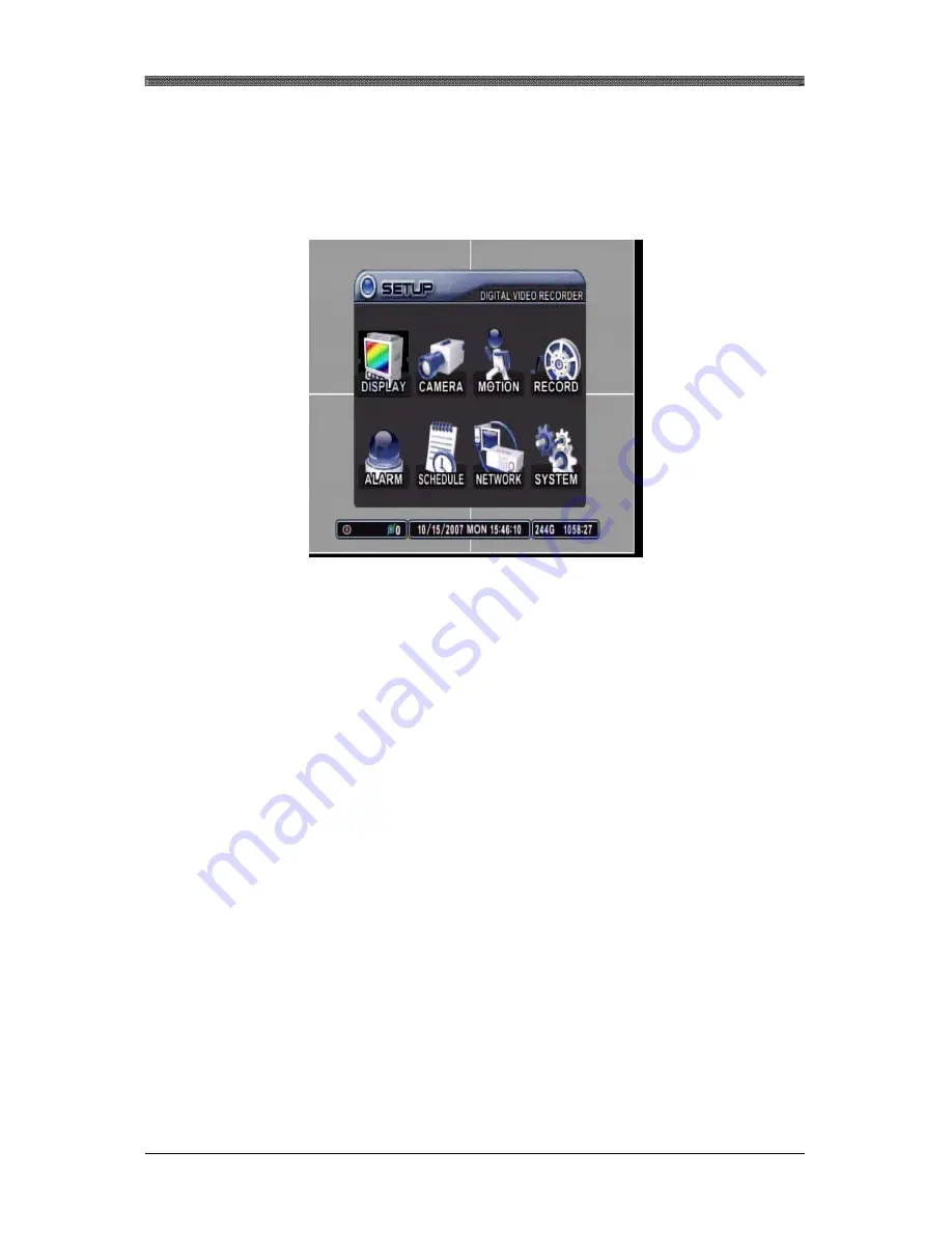
Press the menu button to access the main menu for the advanced settings of the 
DVR. 
 
The menu will display the following categories: 


Directional buttons are used to navigate through all the main categories and their 
submenus.  ENTER button is used to access and save the settings and exit out of 
the submenus.  The – and + buttons are used to select available options.  CANCEL 
button is used to revert back to previous settings and exiting the submenus without 
saving any changes. 

Summary of Contents for PNDVR

Page 1: ...the Digital Video Recorder please ensure that you have read and understood the User Guide Please store the User Guide at an easily accessible location Before connecting and installing any third party...

Page 2: ...the user to the presence of uninsulated dangerous voltage within the product s enclosure that may be of sufficient magnitude to constitute a risk of electric shock to persons The exclamation point wit...

Page 3: ...amage If any components are damaged or missing do not attempt to use the unit contact the vendor immediately CONTENTS QUANTITY REMARK DIGITAL VIDEO RECORDER 1 CLIENT SOFTWARE CD 1 REMOTE CONTROLLER 1...

Page 4: ...DVD BACKUP 32 12 MINI PLAYER 34 13 PAN TILT ZOOM CONTROL 35 14 ADVANCED RECORDING 38 SETUP 45 1 DISPLAY 46 1 1 DISPLAY SETUP 46 1 2 SEQUENTIAL SETUP 47 1 3 SCREEN SAVER 48 2 CAMERA 49 3 MOTION 52 4 R...

Page 5: ...ITE 81 5 CMS LITE LIVE MODE 84 6 CMS LITE PLAYBACK MODE 85 6 1 SEARCH 86 6 2 REMOTE SEARCH 87 6 3 REMOTE PLAYBACK 87 6 4 DOWNLOAD 88 6 5 LOCAL SEARCH 89 6 6 LOCAL PLAYBACK 89 7 DVR SETUP 91 INTERNET E...

Page 6: ...power cable from the power outlet Confirm that smoke and fume emissions have ceased Please consult your DVR distributor Stop operating the equipment if a heavy object is dropped or the casing is damag...

Page 7: ...shock explosion or serious injury Do not attempt to disassemble alter or apply heat to the batteries There is serious risk of injury due to an explosion Immediately flush with water any area of the bo...

Page 8: ...EG 4 DVR 7 QUICK REFERENCE PAGE The Factory Default password for the unit is 000000 SECURITY WARNING Please be sure to change the administrator and user s password from the unit Please refer to page 7...

Page 9: ...d to hide the on screen display information such as time date or channel icons It is also used to remove the alert icons or turn off the alarm buzzer Playback Mode This button is used to pause the fra...

Page 10: ...Fast Forward Step Forward Live Mode This button is used to activate or deactivate the schedule recording or have schedule recording on stand by Playback Mode This button is used to fast forward durin...

Page 11: ...EXT SEARCH is not supported by this model STOP PLAY BACK UP DVR ID MENU LOG FAST FORWARD DISPLAY MODE SCHEDULE REC ON OFF ENTER INFORMATION CANCEL OSD OFF EXT SEARCH REWIND NUMBERS ALPHABET TIME SEAR...

Page 12: ...After connecting the mouse mouse cursor will appear as you move the mouse around the screen INTERFACE BOX Right Click on the mouse to bring up the interface box Please note that the interface box func...

Page 13: ...MPEG 4 DVR 12 DIGITAL VIDEO RECORDER CONNECTIONS 4 REAR PANEL 4 Channel 8 Channel 16 Channel...

Page 14: ...T OUTPUT 1 RCA Audio Input and Output 5 VGA OUTPUT VGA output to PC Monitors to be used as Main Monitor 6 NETWORK PORT 10 100 Base t RJ45 Ethernet Port for Network Connection 7 RS232C PORT For System...

Page 15: ...ne Alarm Sensor and Power Cord Up to 4 cameras CAMERA 1 MIC SENSOR PAN TILT CAMERA PC MONITOR U SB US B MONITOR2 US B MONITOR1 Example of 4 Channel Model Note RS422 485 Connection TX Connect to PTZ ca...

Page 16: ...er the HDD Rack bay and connect IDE first then connect Power Check though the hole if the connection is correct 3 Secure the hard drive by fastening the screws included with the package Tighten the sc...

Page 17: ...Moreover it will also address live view mode that the DVR has to offer Which include automatic sequence mode and digital zoom feature 1 TIME DATE SETTING When the DVR is powered on for the very first...

Page 18: ...el Button to clear the icons from the screen 3 Recording Mode Indicator 4 Camera Number and its Title 5 CD DVD Backup Progress USB Status Recording Mode Audio and Number of Remote Users Connected Icon...

Page 19: ...s The single channel display mode can be accessed directly by pressing the appropriate channel number The rest of the display modes can be accessed sequentially by pressing the display button which ha...

Page 20: ...ntinue to sequence through all the channels in full screen mode if single channel sequencing is selected If any other display sequencing modes are selected then the sequence will move onto the next se...

Page 21: ...m window Press the directional buttons to move the zoom window to the desired location Press the Enter button once more to zoom into the selected area on the screen Use the directional buttons to move...

Page 22: ...endently from the main monitor By pressing onto SPOT from the Remote Control and entering the channel number will bring that specific channel into Full Screen By pressing SPOT button twice all the cha...

Page 23: ...isted and sorted under ALL in chronological order starting with the most recent 7 2 SYSTEM Any event related to the operation of the system is listed and sorted under SYSTEM in the same chronological...

Page 24: ...der ALARM in the same chronological order 7 5 MOTION Any motion activity is listed and sorted under MOTION in the same chronological order 7 6 VIDEO LOSS Any video signal losses or interruptions are l...

Page 25: ...ollow 4 Channel ALL CHANNELS RESOLUTION USE QUALITY RATE AUDIO MOTION 360 x 240 ON ULTRA 7 F S OFF OFF 8 Channel ALL CHANNELS RESOLUTION USE QUALITY RATE AUDIO MOTION 360 x 240 ON ULTRA 7 F S OFF OFF...

Page 26: ...ress the Enter button to access selected date Use the directional buttons to navigate to the desired hour and minute slot To review all 4 channels select a slot from the MINUTE bar and press the Enter...

Page 27: ...ation to the left has selected channel 16 at 00 20 in the morning on January 4 2006 Channel 1 will be displayed in full screen mode starting playback of the data exactly at 16 00 00 in the afternoon o...

Page 28: ...to access the log submenu Use the directional buttons to navigate to the desired log UP and DOWN buttons are used to navigate through the list of the logs and LEFT and RIGHT buttons to navigate throu...

Page 29: ...stration to the left has selected a log from the VIDEO LOSS tab Alarm or motion related playback will display according icons during the playback The illustration to the left is playing back channel 2...

Page 30: ...rations for a detailed description Press the PLAY button and the play icon will be displayed The DVR will start the playback from the latest data if playing back for the first time Press the PLAY butt...

Page 31: ...mode pause the playback by pressing the RIGHT STEP button Keep pressing the RIGHT STEP button to enter the picture by picture mode and to advance and view recorded data one picture at a time Press th...

Page 32: ...recording speeds The audio if recorded is played back automatically when in single channel view mode 10 LOCK The buttons on the DVR can be locked by pressing the LOCK button and then entering the adm...

Page 33: ...and then press the BACKUP button Enter the password when the password prompt appears Select the recorded data type to be included on the backup DVD The illustration to the left has selected NORMAL AL...

Page 34: ...cess Please note that the internal DVD RW icon s color is gray The progress of the backup will be displayed at the bottom of the window in percentages of the entire backup process Please note that the...

Page 35: ...DVR 34 12 MINI PLAYER Upon Backup Mini Player gets copied into the DVD automatically There is no need to install separate software to view the clips For advanced playback options please use the CMS So...

Page 36: ...mber to control the PTZ camera Some PTZ control functions can only be accessed using the remote controller so please have the remote controller handy when using the PTZ control interface The layout of...

Page 37: ...s Enter Start Auto Tour BACKUP on remote controller 1 Press Auto Tour Button 2 Press the button and enter the range of Preset and press Enter 3 For Example Auto Tour Button 5 will start the tour of 1...

Page 38: ...REC on remote controller Exit Menu SCHEDULE on remote controller Sets left pan speed LEFT step button on remote controller Sets right pan speed RIGHT step button on remote controller 13 7 MOVEMENT SPE...

Page 39: ...an be adjusted from the ALARM setup Please note that alarm recording is independent of any recording modes Press the RECORD button and the record icon will appear as shown on the left The DVR will be...

Page 40: ...vated the motion grid setting may be ignored Press the record button and the record icon will appear as shown on the left The DVR will be on record standby mode until motion is triggered The DVR does...

Page 41: ...ecord Please refer to page 71 for setting up schedule recording Press the SCHEDULE button to start recording based on the preconfigured schedule If there is nothing to be run at the time when SCHEDULE...

Page 42: ...of an alarm triggers Both normal recording and alarm recording can be used together to satisfy the needs Normal recording settings has been configured to 1 picture per second Please verify that USE fo...

Page 43: ...irement Motion recording has been activated under RECORD menu The recording rate for motion is at 30 pictures per second ALARM recording has been configured to record at 30 pictures per second Please...

Page 44: ...ng time period The illustration to the left has modified MODE1 to record at 30 pictures per second Please verify that the USE for the camera necessary has been set to ON ALARM recording has been confi...

Page 45: ...res per second Please verify that the USE for the camera necessary has been set to ON The combination of both settings will allow the DVR to record whenever there is a motion detection during the sche...

Page 46: ...gories Directional buttons are used to navigate through all the main categories and their submenus ENTER button is used to access and save the settings and exit out of the submenus The and buttons are...

Page 47: ...P STATUS BAR Select the display of the status bar containing various USB client connection date time remaining hard disk drive size and remaining recording time If set to HIDE then the bar at the bott...

Page 48: ...time Available delay time is from 1 second to 30 seconds per display The default is five seconds SEQ MODE Select what display modes to include in sequenced display Single quad 6 7 8 9 10 13 and 16 cha...

Page 49: ...USE Turns off the signal to the monitor after designated time Default is OFF TIME Configure the time so that the unit goes into screen saver feature on a designated time WAIT Dwell time before the un...

Page 50: ...t between covert mode YES and normal mode NO If covert mode is activated the activated camera s display will be hidden on the monitor However the video is still being recorded When Admin is connected...

Page 51: ...es on cellular phones or keypad driven input systems press the appropriate numeric buttons on the remote controller or on the DVR to enter the desired letters and numbers Refer to the following illust...

Page 52: ...bps 14 PELCO D PROTOCAL 9600 bps 15 CNB AN200 9600bps 16 CANON VC C4 9600bps 17 PELCO P PROTOCOL 2400bps 18 PELCO P PROTOCOL 4800bps 19 PELCO P PROTOCOL 9600bps 20 PELCO Expanded 2400bps 21 PELCO Expa...

Page 53: ...f additional motion is detected during the post record duration then the counter is reset and will record for an additional set time of the RECORD TIME The default value is 40 seconds CAMERA SELECTION...

Page 54: ...ic button All the grids are active by default and are highlighted in blue tint If deactivated then the tint will be removed Press the or button after highlighting the PENCIL icon to activate all grids...

Page 55: ...used to record The default value is ON QUALITY Select from five available record qualities Low Middle High Super and Ultra The default value is HIGH RATE Adjust the record rate for each camera Note th...

Page 56: ...ar camera will not be used to record The default value is ON QUALITY Select from five available record qualities Low Middle High Super and Ultra The default value is HIGH RATE Adjust the record rate f...

Page 57: ...s reset and will record for an additional set time of the RECORD TIME RECORD CAMERA Record camera provides the option of two distinct recording modes when an alarm trigger occurs ALL Any alarm trigger...

Page 58: ...M is selected the relays will be triggered in case of system abnormalities such as HDD FAIL FAN LOCK and so on ALARM OUT ON OFF Enable or disable the alarm relays The default value is OFF 5 3 RECORD E...

Page 59: ...dule by pressing the Schedule button on the front panel after all the values have been entered If no schedule is entered the unit will prompt the user to set the schedule function 6 1 CHART The CHART...

Page 60: ...recording in real life situations EXAMPLE A store owner needs to record from 10am through 8pm every day of the week using continuous recording Additionally the owner needs to record during his non bus...

Page 61: ...11 59pm and then select MODE 2 The DVR does not recognize beyond the actual 24 hour 00 00 23 59 cycle Hence the overnight schedule must be divided into two parts Enter the second part of the non busin...

Page 62: ...MPEG 4 DVR 61 Select MODE 1 and adjust the settings accordingly Select MODE 2 and adjust the settings accordingly Press ENTER button to save and exit to main menu...

Page 63: ...ynamic Host Configuration Protocol a service where the IP address is issued automatically IP ADDRESS If STATIC IP is selected this is where the IP address information is entered as provided by the Int...

Page 64: ...SMTP for your e mail notification option Off DVR does not send e mail notification Default DVR sends e mail notification through dvrhost com SMTP DVR sends e mail notification through private or user...

Page 65: ...ys connect to fixed address DYNDNS The unit communicates with dyndns org for the DDNS service 7 3 2 DOMAIN NAME If DYNDNS is chosen enter the domain name provided by the DYNDNS 7 3 3 USER ID If DYNDNS...

Page 66: ...Select the amount of network bandwidth that the DVR can utilize 7 4 2 PING BLOCK Select On or Off to have the DVR block the ping request 7 4 3 SCAN BLOCK Select On or Off to have the DVR block the Au...

Page 67: ...t Service Provider The purpose of a router is to enable multiple personal computers and any other devices that require internet connection to access the internet simultaneously Most routers by default...

Page 68: ...n Internet Explorer then type in http 192 168 1 1 to access the router Enter the User Name and Password to access the router You will then be taken to the main menu The factory user name is blank and...

Page 69: ...MPEG 4 DVR 68 Click on Application Gaming tab to access port forwarding configuration page...

Page 70: ...ignated port 7000 for the DVR Point each port to the DVR Illustration shows that the DVR s IP address being 192 168 1 251 In the following examples DVR7000 was used Make sure you enable the port forwa...

Page 71: ...NG THE DVR TO COMMUNICATE WITH A LINKSYS ROUTER Go to Network in Main Menu Set the CONFIG as STATIC IP Make sure to change the information to IP ADDRESS 192 168 001 251 NETMASK 255 255 255 000 GATEWAY...

Page 72: ...re the Network Address of this DVR is as follows L51337F DVRHOST COM 7000 L51337F Unique permanent ID of this DVR DVRHOST COM Free DDNS Service 7000 Port that was set under the Network Section You can...

Page 73: ...d using one remote controller To select the DVR to be controlled with the remote controller press and hold the DVR ID button While holding the DVR ID button press the appropriate DVR ID number For exa...

Page 74: ...mpt for password when required such as entering Menu or stopping record 8 2 TIME 8 2 1 TIME SYNC If the DVR is connected to the network and if there are more than one DVR connected then a DVR can be c...

Page 75: ...The DVR can differentiate and recognize different rights to different users Highlight the appropriate user and configure their privilege 8 3 2 ACTIVATE Activate the User 1 5 8 3 3 PRIVILEGE Check or...

Page 76: ...o begin formatting 8 4 2 INTERNAL HDD Select the record policy of the internal hard disk drive By default the hard disk drive will overwrite from the beginning when it becomes full 8 4 3 DISK MONITOR...

Page 77: ...e and upgrade file present on the USB Thumbdrive 8 5 2 BOARD VERSION Displays the unit s Board Version 8 5 3 FPGA VERSION Displays the unit s FPGA Version 8 5 4 BIOS VERSION Displays the unit s BIOS V...

Page 78: ...perating language 8 6 4 NETWORK Displays the unit s IP Address 8 6 5 INTERNAL HDD Displays the total HDD and its total capacity 8 6 6 RACK DEVICE Displays the connected Rack Device 8 6 7 USB FRONT Dis...

Page 79: ...minimum and the recommended system specification to operate the CMS properly Recommended OS Windows XP CPU Pentium IV 2 8 GHz RAM 512MB RAM Video Card 16MB Free Space 2 GB Resolution 1024x768 DirectX...

Page 80: ...hortcuts The Start Menu Shortcuts and Desktop Shortcuts may be unchecked if desired Click on Next to continue Select the folder in which the program will be installed By default it is installed in C P...

Page 81: ...ress of the DVR or the hostname 2 Enter the Port Number of the DVR Port 7000 is the Default 3 Enter either the Admin or User Password of the DVR 4 Select the Video mode either NTSC or PAL NTSC is the...

Page 82: ...in window When the actual video is displayed it will display the channel number and title as well as the frame rate 2 CAMERA DISPLAY SELECTION From the top single 4 channel 6 channel 7 channel 8 chann...

Page 83: ...le format In addition you can print the image from your local printer 6 CAMERA SELECTOR Select specific camera to go into full screen 7 PAN TILT ZOOM CONTROL If one or more Pan Tilt Zoom cameras are i...

Page 84: ...MPEG 4 DVR 83...

Page 85: ...DVR 3 Displays DVR Status REC Normal Recording Wait Initial Connection Loss Video Loss Close Disconnected from the DVR Alarm Alarm Recording Motion Motion Recording PB Playback for selected channel Li...

Page 86: ...by clicking on any camera number The same can be done by double clicking on any channels 2 Playback Speed During playback the images can be paused fast forward fast reverse It can also be in a frame...

Page 87: ...y Displays different types of recording for each hour and minute slot Yellow Normal Recording Green Motion Recording Red Alarm Recording 6 Play and Download Play Start live playback Download the video...

Page 88: ...MPEG 4 DVR 87 6 2 REMOTE SEARCH Click on the Remote Search Icon 6 3 REMOTE PLAYBACK Select the date and the time Click on PLAY to begin the remote playback...

Page 89: ...in time You can also change the speed of the playback 6 4 DOWNLOAD The file selection process is just as selecting a slot for remote playback To download the file click on Download instead of Play The...

Page 90: ...MPEG 4 DVR 89 Once the download is complete Download Complete will be displayed 6 5 LOCAL SEARCH Click on Local Search Icon 6 6 LOCAL PLAYBACK Select the date and the time...

Page 91: ...MPEG 4 DVR 90 The Hour Minute and the Clip can be clicked at any time to move backward or forward in time You can also change the speed of the playback...

Page 92: ...PEG 4 DVR 91 7 DVR SETUP The DVR Setup allows modification of all system settings through CMS Lite as it would be done accessing the DVR menu screen Please refer to Page 45 for explanation of the Setu...

Page 93: ...UNIT VIA INTERNET EXPLORER 1 1 ENTER THE ADDRESS Enter the IP address of the unit in the address pane of the Internet Explorer For example type in http 192 168 0 85 7000 Above illustrates example of...

Page 94: ...MPEG 4 DVR 93 If connecting to the unit for the first time click on Install ActiveX Control so that the plug in are loaded Click on Install When the Image Loading is done the images should appear...

Page 95: ...MPEG 4 DVR 94 Notes...

Reviews: