background image

 ISSUED: 04-01-08  SHEET #: 055-9254-3 05-29-08

6 of 12

Visit  the  Peerless  Web  Site  at  www.peerlessmounts.com

For Technical Support Contact Peerless Mounts at 1-800-729-0307 or 708-865-8870.

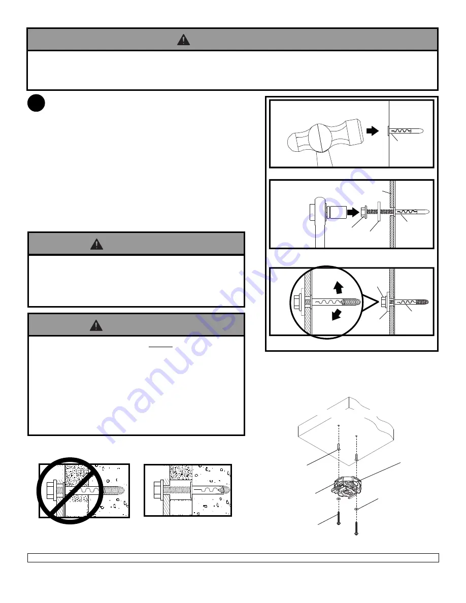
Place projector mount assembly (

A

) on ceiling as a

template and mark the center of the two mounting holes.
Drill two 1/4" (6 mm) dia. holes to a minimum depth of 2.5"
(64 mm). Attach projector mount assembly (

A

) using two

Alligator

® 

 concrete anchors (

H

), two flat washers (

K

), and

two #14 x 2.5" wood screws (

L

) as shown in 

Illustration A

and

 1

2

 and 

3

).

NOTE: 

Mounting slots on projector mount assembly allow

for 30° (±15°) of swivel adjustment before fully securing
wood screws.

Tighten wood screws (

L

) using 3/8" (10 mm) socket or

open end wrench or phillips screwdriver until projector
mount assembly (

A

) is firmly attached.

Installation to Concrete Ceilings

1

• Concrete must be 2000 psi density minimum. Lighter density concrete may not hold concrete anchor.

• Make sure that the supporting surface will safely support the combined load of the equipment and all attached hard-

ware and components.

WARNING

1

3

Drill hole and insert anchor

CONCRETE
CEILING

L

L

2

A

H

H

H

Place mount over anchor and secure with screw and
washer

After repeating step one tighten all fasteners

CUT

A

W

A

Y

 VIEW

INCORRECT

concrete

plaster/
dry wall

CORRECT

concrete

plaster/
dry wall

A

A

Illustration A

H

L

K

A

CONCRETE CEILING

K

K

• Always attach concrete anchors directly to load-bearing

concrete.

• Never attach concrete anchors to concrete covered with

plaster, drywall, or other finishing material. If mounting to
concrete surfaces covered with a finishing surface is
unavoidable, the finishing surface must be counterbored as
shown below. Be sure concrete anchors do not pull away
from concrete when tightening screws. If plaster/drywall is
thicker than 5/8", custom fasteners must be supplied by
installer (not UL approved).

• Tighten wood screws firmly, but do not overtighten.

Overtightening can damage the screws, greatly reducing
their holding power.

• Never tighten in excess of 80 in • lb (9 N.M.).

WARNING

WARNING

ARROW
INDICATES
FRONT OF
MOUNT

Summary of Contents for ELPMBPRG

Page 1: ...h Ave Melrose Park IL 60160 800 865 2112 or 708 865 8870 Fax 708 865 2941 www peerlessmounts com Maximum UL Load Capacity 50 lb 22 7 kg This product is UL Listed It must be installed by a qualified pr...

Page 2: ...position equipment This product is intended for indoor use only Use of this product outdoors could lead to product failure and personal injury Tighten screws firmly but do not overtighten Overtighten...

Page 3: ...55 2804 B adapter plate 1 055 2806 C dedicated adapter plate 1 055 2871 D M4 x 20 mm socket pin serrated washer head screw 4 510 2163 E M5 x 20 mm socket pin serrated washer head screw 4 510 2065 F 3...

Page 4: ...igure 1 1 NOTE Swivel stop screw is used to jam against threads of extension column or flush mount tube to prevent any excess movement of projector mount assembly A as shown in detail 1 Do not overtig...

Page 5: ...river until projector mount assembly A is firmly attached Skip to step 2 L L A WOOD JOIST K K WOOD JOIST A ACCESS SLOT FOR OPENENDWRENCH ALLOWSTIGHTENING OF WOOD SCREW L 1 Installation To Wood Joist C...

Page 6: ...he supporting surface will safely support the combined load of the equipment and all attached hard ware and components WARNING 1 3 Drill hole and insert anchor CONCRETE CEILING L L 2 A H H H Place mou...

Page 7: ...te B as shown Continue to step 3 2 Plate Horizontal Configuration PowerLite Pro G5200WNL G5350NL G5150NL 6110i Attach adapter plate B plate C using six M4 x 6 mm socket pin screws G G B C 2 All spacer...

Page 8: ...83 400W 822 1810p 1825 S6 78 W6 2 NOTE SHOULDER INDICATESTHEBACKOF ADAPTER PLATE B FRONT FRONT FRONT FRONT FRONT NOTE Shoulder indicates back of adapter plate B Flip projector upside down Find your pr...

Page 9: ...t assembly A as shown Tighten captive screw to secure projector to projector mount assembly A IMPORTANT For security installations insert one 10 32 x 1 4 socket pin screw I through projector mount ass...

Page 10: ...1 Route cables through top of extension column as shown in figure 5 2 and figure 5 3 NOTE A method for assisting cables through extension column may be required example string tied to connector to hel...

Page 11: ...hand for easy adjustment or insert 2 phillips screwdriver in end of knob and turn SCREW FOR SWIVEL STOP KNOB FOR ROLL ADJUSTMENT KNOB FOR PITCH ADJUSTMENT BACKOFMOUNT To prevent tampering with the pit...

Page 12: ...ULVLQJ IURP WKH WKHIW RI DQ SURGXFW ZKHWKHU RU QRW VHFXUHG E D VHFXULW GHYLFH ZKLFK PD EH LQFOXGHG ZLWK WKH SURGXFW 7KLV LPLWHG LYH HDU DUUDQW LV LQ OLHX RI DOO RWKHU ZDUUDQWLHV H SUHVVHG RU LPSOLHG D...

Reviews: