MN-36956/MM-1074
Rev 0 (01/15) • Blanket Warming Cabinet Operation & Care Manual • 20
NOTE:
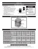
If your unit is not operating properly, check the following before calling your authorized service agent . Check the power applied to the unit .
Verify female end of plug is securely seated in unit and that the male end of plug is in an appropriate, functioning outlet . Check fuses . (See “Fuse
Replacement” section in manual .)
Do not attempt to repair or service beyond this point . Contact manufacturer for nearest authorized service agent . Repairs made by any other
service agent without prior authorization by manufacturer will void the warranty on the unit .
This chart is provided for the assistance of qualified technicians only and is not intended for use by untrained or unauthorized service personnel .
Blanket warmer temperature may fluctuate
±
10° from set point .
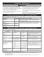
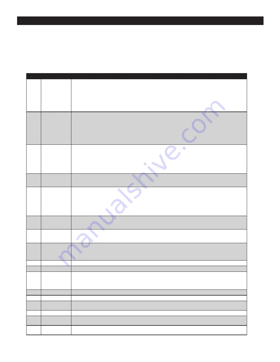
T R O U B L E S H O O T I N G G U I D E
Code
Refers to
Action Required
E-10
ES10
ES20
ES30
ES40
ES50
ES60
ES70
Cavity sensor
Sensor 1
Sensor 2
Sensor 3
Sensor 4
Sensor 5
Sensor 6
Sensor 7
Sensor is shorted . Software disengages heating pads . User must acknowledge error by pressing ON/OFF button . If
error persists, a qualifi ed service technician should test sensor.
• To test sensor: Detach the sensor from unit . Use an Ohm meter to measure the resistance of the sensor . Check
sensor at 0°C (32°F) using a container of ice water . If reading is 32 .6 KOhm ±1 .5 KOhm, replace display . If reading
is ±2 KOhm, replace sensor .
• Check wires for integrity . Check for proper and secure connections at the control and terminal block . If necessary,
re-secure the faulty connections .
• Call service if error persists .
E-11
ES11
ES21
ES31
ES41
ES51
ES61
ES71
Cavity sensor
Pad sensor 1
Pad sensor 2
Pad sensor 3
Pad sensor 4
Pad sensor 5
Pad sensor 6
Pad sensor 7
Sensor is open . Software disengages heating pads . User must acknowledge error by pressing ON/OFF button . If error
persists, a qualifi ed service technician should test sensor.
• To test sensor: Detach the sensor from unit . Use an Ohm meter to measure the resistance of the sensor . Check
sensor at 0°C (32°F) using a container of ice water . If reading is 32 .6 KOhm ±1 .5 KOhm, replace display . If reading
is ±2 KOhm, replace sensor .
• Check wires for integrity . Check for proper and secure connections at the control and terminal block . If necessary,
re-secure the faulty connections .
• Call service if error persists .
P130
P230
P330
P430
P530
P630
P730
Pad 1
Pad 2
Pad 3
Pad 4
Pad 5
Pad 6
Pad 7
Heating pad has not reached set-point temperature . User must acknowledge error by pressing ON/OFF
button. If error persists, a qualifi ed service technician should test the heater pad(s).
• Turn unit OFF and unplug it from AC power .
• Use Ohm meter to measure resistance between L:(Line) & N:(Neutral) leads of a cold heater pad .
–
The Ohm readings shall be: 120V = 72 Ohm ±10% or 230V = 288 Ohm ±10%
• Call service if error persists .
*E-31
Cavity sensor
• Sensor reading is above maximum allowable temperature set-point .
–
Fluid Warmers, triggers at 5° over set point . Blanket Warmers, triggers at 15° over set point
• Call service .
P131
P231
P331
P431
P531
P631
P731
Pad sensor 1
Pad sensor 2
Pad sensor 3
Pad sensor 4
Pad sensor 5
Pad sensor 6
Pad sensor 7
Heater pad over-temp error
• Software disengages heating pads .
• User must acknowledge error by pressing ON/OFF button .
• Allow unit to cool .
• Call service if error persists .
*E-33
Cavity sensor
• Sensor reading is above maximum allowable temperature set-point and over temp value
–
Fluid Warmers, triggers at 71°C (160°F) . Blanket Warmers, triggers at 79°C (175°F)
• Contact service
*E-50
Analog to Digital
Convertor Error
• Remove product and allow unit to cool down. Inspect fl uid and discard if necessary.
• If error persists after cool down and reset, control assembly should be replaced by a qualifi ed service technician.
Contact service .
E-60
Real Time Clock
Checksum Error
(Blanket Warmers Only)
Real Time Clock rechargeable battery backup has discharged .
• Plug unit into outlet for 30 minutes .
• See “Timer Control Panel” section in blanket manual to reset clock .
*E-61
Real Time Clock
(Blanket Warmers Only)
Real Time Clock not responding . Call service if error persists .
E-62
Real Time Clock
Timer overlay is present, but no real time clock is detected . Call service .
*E-70
Pad Count Error
More heater pads detected than set for . Hold ON/OFF button for 12 seconds until display shows "PAd#”
(# = number of pads selected [3-7]) . Press UP or DOWN arrow to adjust to correct number of pads .
–
Fluid Warmers: DC250L & DC400L = 3 pads
–
Blanket Warmers: DC150, DC250, & EC250 = 3 pads, DC350, DC400, EC350, DC750 & EC750 = 4 pads
*E-71
Personality Error
Call service
E-80
EEPROM Error
EEPROM not responding . Call service if error persists .
*E-81
Calibration
not locked
Call service
*E-83
EEPROM Error
Call service for help resetting the control .
E-87
EEPROM Error
Stored offsets corrupted . Offsets reset to 0 . Control may need to be recalibrated . Possible bad EEPROM .
Call service if error persists .
E-90
Button stuck
A button has been held down for >60 seconds . Adjust control . Error will reset when the problem has
been resolved .
E-95
Factory Test pin
short detected .
Ensure no debris is causing a short between the test pins . If pins are good, replace control .
*E-98
Temperature
Delta Error
(Fluid Warmers Only)
Temperature of cavity sensors 1 and 2 differ by more than 1 .7ºC (3ºF) .
• Remove product and allow unit to cool down .
• Verify that product sensor is clean and operating correctly .
• Press power button to clear error code .
• If error persists, the sensor switch assembly should be replaced by a qualified service technician. Contact service.
E-99
Hardware
Over Temp
• Inspect connections and condition of high limit bimetal thermostat .
• If error continues call service .
*EFAn
Fan or Fan Sensor
failure
(Fluid Warmers Only)
• If the fan is operating, ensure that the lens on the sensor is not blocked or dirty .
• If error persists after cleaning sensor, use an Ohm meter to ensure sensor wires are good . A good wire will have a
reading of <1 Ohm .
• If wires are good, replace sensor .
• If error persists after replacement, check sensor mount location .
• If error still persists, replace control .
Note:
All non-critical codes can be cleared using the ON/OFF button . Critical errors (marked with a *) can only be cleared by turning the power switch
on the back of the unit off and allowing unit to cool .

