background image

*  Fetch out the battery when the meter will not be used for long 

period. 

*  Periodically  wipe  the  cabinet  with  a  damp  cloth  and  mid 

detergent. Do not use abrasives or solvents. 

*  The meter is suitable for indoor use only  
*  Do  not  operate  the  meter  before  the  cabinet  has  been  closed 

and screwed safely as terminal can carry voltage. 

*  Do  not  store  the  meter  in  a  place  of  explosive,  inflammable 

substances. 

*  Do not modify the meter in any way. 
*  Opening the equipment and service- and repair work must only 

be performed by qualified service personnel. 

Measuring instruments don’t belong to children hands. 


1.1. Safety Symbols 

The following symbols are imprinted on the front panel of the meter 
to remind you of measurement limitations and safety. 


10 A 

The  maximum  current,  that  you  can  measure  a  this 
terminal is 10A DC/AC. This terminal is fuse protected 
by F 10 A/250V fuse. When using this range with high 
current,  keep  the  duty  cycle  to  30  seconds  on  load 
and 15 minutes off load. 

 
µA/mA 

The  max.  current,  that  you  can  measure  with  this 
terminal  is  400  mA,  that  is  fuse  protected  by  1mA  / 
250V fuse. 

  max. 


To avoid electrical shock or instrument damage, do 
not connect the C Common Input COM terminal to 
any source of 1000V DC/AC with respect to earth 
ground. 


Be  exceptionally  careful  when  measuring  high 
voltages. Do not touch the terminals or test lead ends.  


Refer to the complete operating instructions! 


Indicates protection class II, double insulation 

CAT III / IV  Overvoltage category III / IV 


-33- 

Summary of Contents for 3315 USB

Page 1: ...PeakTech 3315 USB Bedienungsanleitung Operation manual Digital Multimeter ...

Page 2: ...nd Hierunter fallen z B Hauptschalter am Stromeingang Überspannungs ableiter Stromverbrauchszähler und Rundsteuer empfänger Zur Betriebssicherheit des Gerätes und zur Vermeidung von schweren Verletzungen durch Strom oder Spannungsüberschläge bzw Kurzschlüsse sind nachfolgend aufgeführte Sicherheitshinweise zum Betrieb des Gerätes unbedingt zu beachten Schäden die durch Nichtbeachtung dieser Hinwei...

Page 3: ...n oder Sicherungen 10A oder 2000VA vornehmen Bei der Widerstandsmessungen keine Spannungen anlegen Keine Strommessungen im Spannungsbereich V Ω vornehmen Gerät Prüfleitungen und sonstiges Zubehör vor Inbetriebnahme auf eventuelle Schäden bzw blanke oder geknickte Kabel und Drähte überprüfen Im Zweifelsfalle keine Messungen vornehmen Messarbeiten nur in trockener Kleidung und vorzugsweise in Gummis...

Page 4: ...fleuchtet Mangelnde Batterieleistung kann unpräzise Messergebnisse hervorrufen Stromschläge und körperliche Schäden können die Folge sein Sollten Sie das Gerät für einen längeren Zeitraum nicht benutzen entnehmen Sie die Batterie aus dem Batteriefach Säubern Sie das Gehäuse regelmäßig mit einem feuchten Stofftuch und einem milden Reinigungsmittel Benutzen Sie keine ätzenden Scheuermittel Dieses Ge...

Page 5: ...ngang ist mit einer Sicherung 1 A 250 V abgesichert max max zulässige Spannungsdifferenz von 1000V DC AC zwischen COM Eingang und Erde aus Sicherheitsgründen nicht überschreiten Gefährlich hohe Spannung zwischen den Eingängen Extreme Vorsicht bei der Messung Eingänge und Messspitzen nicht berühren ACHTUNG Entsprechende Abschnitte in der Bedienungsanleitung beachten Doppelt isoliert Schutzklasse II...

Page 6: ...Eingangsbuchsen max zulässige Eingangs spannung bzw strom V DC V Ω Hz COM 1000 V DC 750 V ACeff V AC 1000 V DC 750 V ACeff Ω 600 V DC AC mA DC AC µA mA COM 1 A 250 V DC AC 10 A DC AC 10 A COM 10 A 250 V DC AC V Ω Hz COM 600 V DC ACss Frequenz 600 V DC ACss Temperatur 600 V DC ACss Kapazität 600 V DC ACss 5 ...

Page 7: ...die Arbeit mit diesem Gerät Messwert Haltefunktion DATA HOLD Minimal Maximalwert Haltefunktion Automatische Polaritätsumschaltung Relativwertmessung Überlast und Überspannungsschutz USB oder RS 232 C Schnittstelle für die Kommunikation mit einem PC Hintergrundbeleuchtung Batteriezustandsanzeige leuchtet im Anzeigefeld bei unzureichender Batterie spannung Summer ertönt zur Warnung bei Überlast bei ...

Page 8: ...tomatik nach 30 Minuten Betriebstemperatur 5 C 40 C bereich Lagertemperaturbereich 10 C 50 C Temperaturbereich für 18 C 28 C 70 RH Genauigkeit Batteriezustandanzeige Batteriesymbol Spannungsversorgung 9V Batterie Abmessungen 90 B x 195 H x 39 T mm Gewicht 550g mitgel Zubehör 1 Satz Prüfleitungen Batterie Temperaturfühler USB und RS 232 C Schnittstellenkabel und Software 7 ...

Page 9: ...enauigkeit Überspannungs schutz 4 V 1 mV 1 5 St 1000 V DC 750 V AC 40 V 10 mV 400 V 100 mV 750 V 1 V 1 2 5 St Eingangswiderstand 10MΩ Zeigt den effektiven Wert der Sinuswelle an Frequenz 40Hz 400Hz 3 3 Gleichstrommessungen Bereich Auflösung Genauigkeit Überspannungs schutz 400 µA 100 nA 1 2 St 1 A 250 V 4000 µA 1 µA 40 mA 10 µA 1 2 3 St 400 mA 100 µA 10 A 10 mA 1 5 5 St 10 A 250 V 10A Bereich Für ...

Page 10: ... Zeigt den effektiven Wert der Sinuswelle an 10A Bereich Für dauerhafte Messungen 10 Sekunden und Intervall Messungen nicht weniger als 15 Minuten Frequenz 40Hz 400Hz 3 5 Widerstandsmessung Bereich Auflösung Genauigkeit Überspannungs schutz 400 Ω 0 1 Ω 1 2 2 St 600 Vss 4 kΩ 1 Ω 1 2 St 40 kΩ 10 Ω 400 kΩ 100 Ω 4 MΩ 1 kΩ 1 2 2 St 40 MΩ 10 kΩ 1 5 2 St 400 Ω Ω Ω Ω 40 MΩ Ω Ω Ω Bereich Leerlaufspannung c...

Page 11: ...t 40 mF 10 µF 40 mF Bereich Anzeige ist nur für Referenzzwecke 3 7 Diodentest Bereich Auflösung Leerlauf spannung Überspannungs schutz 4 V 1 mV 3 V 600 Vss 3 8 Frequenzmessungen Bereich Auflösung Genauigkeit Überspannungs schutz 4 kHz 1 Hz 0 1 3 St 600 Vss 40 kHz 10 Hz 400 kHz 100 Hz 4 MHz 1 kHz 40 MHz 10 kHz 400 MHz 100 kHz Eingangs Empfindlichkeit 40MHz 200 mVeff 100MHz 1 Veff 100MHz Nur Referen...

Page 12: ...keit 40 C 1000 C 1 C 40 C 0 C 3 4 St 0 C 400 C 1 3 St 400 C 1000 C 2 10 St 40 F 1832 F 1 F 40 F 32 F 3 4 St 32 F 752 F 1 4 St 752 F 1832 F 2 5 Überspannungsschutz 600Vss 3 10 Durchgangsprüfung Summer ertönt bei weniger als 40Ω Überlastschutz 600Vss 11 ...

Page 13: ...4 Bedienelemente und Anschlüsse am Gerät 12 1 9 11 12 10 2 3 4 8 13 7 14 5 6 ...

Page 14: ...aufgenommen Drücken Sie die HOLD Taste erneut um wieder in den MAX MIN Modus zugelangen 9 Maximal und Minimalwerthaltefunktion Zum Ermitteln des maximalen bzw des minimalen Messwertes wie beschrieben verfahren Drücken Sie die Taste MIN MAX um den maximalen Messwert anzugeigen MAX Symbol erscheint in der Anzeige Drücken Sie MAX MIN erneut um minimalen Messwert anzuzeigen MIN Symbol erscheint in der...

Page 15: ...rüfung 14 Range Taste Bereichswahl Abschaltautomatik Die integrierte Abschaltautomatik des Gerätes schaltet das Gerät nach 30 Minuten ohne Bedienung ab um die Batterie zu schonen Diese Abschaltautomatik ist auch abschaltbar z B für Dauermessungen mit der mitgelieferten Software Um die Abschaltautomatik zu deaktivieren gehen sie wie folgt vor Schalten Sie das Gerät ein und drücken Sie gleichzeitig ...

Page 16: ...oten Prüfleitung bei AC DC Strommessungen bis max 10A Funktions Bereichs wahlschalter in Stellung 10A 7 Data Hold Funktion Die Data Hold Funktion ermöglicht das Einfrieren eines Messwertes zum späteren Ablesen in der LCD Zur Aktivierung der Data Hold Funktion HOLD Taste drücken bis das Symbol HOLD im Anzeigefeld erscheint 8 Hintergrundbeleuchtung Die Hintergrundbeleuchtung dient zum besseren Ables...

Page 17: ...matisch der richtige Bereich und die beste Auflösung gewählt wird 2 Batteriezustandsanzeige 3 Polaritätsanzeige 4 Diodentestfunktion 5 Durchgangsprüfung 6 Relativwert Messung 7 Data Hold 8 Anzeige für Gleichspannung oder strom 9 Anzeige für Wechselspannung oder strom 16 10 alle anderen ...

Page 18: ...enheit einer in Erster Hilfe ausgebildeten Person stattfinden Achtung Die maximal zulässige Eingangsspannung des Gerätes beträgt 1000V DC oder 750V AC und darf aus Sicherheitsgründen nicht überschritten werden Die maximal zulässige Spannungsdifferenz zwischen dem COM Eingang und Erde beträgt 1000V DC AC Bei größeren Spannungsdifferenzen besteht Verletzungsgefahr durch elektrischen Schlag und oder ...

Page 19: ...er richtige Messwert angezeigt WARNUNG Maximal zulässige Eingangsspannung von 1000V DC oder 750V AC nicht überschreiten Bei Überschreitung besteht die Gefahr schwerer Verletzungen durch Stromschlag und oder die Gefahr der Beschädigung des Gerätes 1 Funktions Bereichswahlschalter in die für Gleich oder Wechselspannungsmessung erforderliche Stellung drehen V Bei unbekannten Messwerten mit dem höchst...

Page 20: ...es Gerätes Zur Durchführung von Strommessungen zu messende Schaltung unterbrechen und Prüfleitungen an zwei Anschlusspunkte anlegen Niemals die Prüfleitungen parallel über eine Spannungsquelle anlegen Dies kann zu einem Ansprechen der Sicherung und Zerstörung der zu prüfenden Schaltung führen Hinweis Der maximale Eingangsstrom beträgt 4000µA 400mA und 10A abhängig von der benutzen Eingangsbuchse B...

Page 21: ...er eine Spannungsquelle anlegen Widerstandsmessungen nur an spannungsfreien Schaltungen bzw Bauteilen vornehmen und alle Kondensatoren entladen 1 Mit dem Funktions Bereichswahlschalter die Ω Position wählen 2 Rote Prüfleitung an den V Ω Hz Eingang und schwarze Prüfleitung an den COM Eingang anschließen 3 Prüfleitungen über die zu messende Schaltung bzw das zu messende Bauteil anlegen Hinweise Bei ...

Page 22: ...n auf Durchlässigkeit und Kurzschlüsse Ebenfalls erlaubt diese Funktion die Durchlassspannung von Dioden zu ermitteln 1 Funktions Bereichswahlschalter in Stellung drehen 2 Rote Prüfleitung an den V Ω Hz Eingang und schwarze Prüfleitung an den COM Eingang anschließen 3 Prüfleitungen über die zu prüfende Diode anlegen und Messwert in der LCD Anzeige ablesen Hinweise Wenn in der LCD Anzeige ein Messw...

Page 23: ...altung spannungslos schalten 5 Prüfleitungen über das zu messende Bauteil bzw die zu messende Schaltung anlegen Bei Widerständen unter 40 Ω Bauteil durchgängig ertönt ein akustisches Signal ACHTUNG Unter keinen Umständen Durchgangsprüfungen an spannungs führenden Bauteilen oder Schaltungen vornehmen 6 6 Frequenzmessung Warnung Keine Messungen an Schaltungen mit Spannungen über 600V AC durchführen ...

Page 24: ...eitungen nicht über eine Spannungsquelle anlegen Kondensatoren vor der Messung immer entladen 1 Funktionsbereichswahlschalter in Stellung drehen 2 Rote Prüfleitung an den V Ω Hz Eingang und schwarze Prüfleitung an den COM Eingang anschließen 3 Wählen Sie mit der Range Taste den gewünschten Mess bereich 4 Drücken Sie die REL Taste um einen Nullabgleich der Anzeige durchzuführen 5 Legen Sie die Prüf...

Page 25: ... der Batterie Das Gerät erfordert eine 9V Blockbatterie Bei ungenügender Batteriespannung leuchtet das Batteriesymbol auf Die Batterie ist dann baldmöglichst aus dem Batteriefach zu entfernen und durch eine neue Batterie zu ersetzen ACHTUNG Vor Abnahme des Gehäuses unbedingt alle Prüfleitungen von der Schaltung entfernen und Gerät ausschalten 24 ...

Page 26: ...fsetzen und mit 3 Schrauben befestigen 6 Achtung Verbrauchte Batterien ordnungsgemäß entsorgen Verbrauchte Batterien sind Sondermüll und müssen in die dafür vorgesehenen Sammelbehälter gegeben werden Achtung Gerät nicht mit offenem Batteriefach benutzen Hinweis Niemals eine defekte oder verbrauchte Batterie im Messgerät belassen Auch auslaufsichere Batterien können Beschädigungen durch auslaufende...

Page 27: ... geben Sie sie im Handel vor Ort kostenlos ab Von uns erhaltene Batterien können Sie nach Gebrauch bei uns unter der auf der letzten Seite angegeben Adresse unentgeltlich zurückgeben oder ausreichend frankiert per Post an uns zurücksenden Sie finden diese Hinweise auch noch einmal in den Begleitpapieren der Warensendung oder in der Bedienungsanleitung des Herstellers Weitere Hinweise zur Batteriev...

Page 28: ...r Sicherungen darf nur durch qualifiziertes Fachpersonal erfolgen Zum Auswechseln der Sicherung wie folgt verfahren 1 Multimeter ausschalten und alle Prüfleitungen von den Eingängen abziehen 2 Die 3 Schrauben im Gehäuseunterteil lösen und Unterteil abziehen 3 Defekte Sicherung entfernen und neue Sicherung gleichen Anschlusswertes und Abmessungen in den Sicherungshalter einsetzen Beim Einsetzen dar...

Page 29: ...en seriellen PC Anschluss oder USB Anschluss 8 2 Installation des PeakTech 3315 Interface Program Zur Installation des Interface Programms beachten Sie bitte die folgenden Schritte 1 Legen Sie die mitgelieferte CD ROM in Ihr CD ROM oder DVD Laufwerk Doppelklicken Sie auf Arbeitsplatz auf Ihrem Windows Desktop Doppelklicken Sie auf das Symbol Ihres CD ROM oder DVD Laufwerks um das Verzeichnis P 331...

Page 30: ... seriellen Anschluss an Ihrem Computer 2 Drücken Sie die RS 232 Taste zum Aktivieren der Schnittstelle 3 Klicken Sie auf die Schaltfläche START und öffnen Sie Ihr Windows Startmenü wählen Sie Programme P 3315 Interface Program P 3315 4 Klicken Sie auf P3315 EXE in der Menüleiste der Software und wählen Sie zwischen COM 1 2 3 4 wenn Sie eine RS 232C Verbindung verwenden oder drücken Sie USB Connect...

Page 31: ... mit schriftlicher Genehmigung des Herausgebers gestattet Letzter Stand bei Drucklegung Technische Änderungen des Gerätes welche dem Fortschritt dienen vorbehalten Hiermit bestätigen wir dass alle Geräte die in unseren Unterlagen genannten Spezifikationen erfüllen und werkseitig kalibriert geliefert werden Eine Wiederholung der Kalibrierung nach Ablauf von 1 Jahr wird empfohlen PeakTech 07 2012 th...

Page 32: ...i e main switches on current input overvoltage diverter current use counter To ensure safe operation of the equipment and eliminate the danger of serious injury due to short circuits arcing the following safety precautions must be observed Damages resulting from failure to observe these safety precautions are exempt from any legal claims whatever Do not use this instrument for high energy industri...

Page 33: ... tips of the test leads or probe Comply with the warning labels and other info on the equipment Always start with the highest measuring range when measuring unknown values Do not subject the equipment to direct sunlight or extreme temperatures humidity or dampness Do not subject the equipment to shocks or strong vibrations Do not operate the equipment near strong magnetic fields motors transformer...

Page 34: ... imprinted on the front panel of the meter to remind you of measurement limitations and safety 10 A The maximum current that you can measure a this terminal is 10A DC AC This terminal is fuse protected by F 10 A 250V fuse When using this range with high current keep the duty cycle to 30 seconds on load and 15 minutes off load µA mA The max current that you can measure with this terminal is 400 mA ...

Page 35: ...e European Union 1 2 Input Limits Function Terminal Input Limits V DC V Ω Hz COM 1000 V DC 750 V ACrms V AC 1000 V DC 750 V ACrms Ω 600 V DC AC mA DC AC µA mA COM 1 A 250 V DC AC 10 A DC AC 10 A COM 10 A 250 V DC AC V Ω Hz COM 600 V DC ACpp Frequency 600 V DC ACpp Temperature 600 V DC ACpp Capacitance 600 V DC ACpp 34 ...

Page 36: ...old Function freezes the display so you can keep the measured value there even after you disconnect the probes Min Max function Auto polarity operation Relative measurement Overload and Transient protection RS 232 C or USB interface for communication to the PC Backlight Low Battery indicator appears when you need to replace the batteries Beeper sounds for overload warning continuity function and r...

Page 37: ...ower off after 30 minutes Operating temperature 5 C 40 C 41 F 104 F Storage temperature 10 C 50 C 14 F 122 F Temperature for guaranteed accuracy 18 C 28 C 70 RH Low battery indication Battery symbol Battery Type Standard 9V battery Dimensions 90 W x 195 H x 39 D mm Weight 550g Accessories Test leads operating manual battery thermocouple RS 232 C and USB interface cable software 36 ...

Page 38: ... Overload protection 4 V 1 mV 1 5 dgt 1000 V DC 750 V AC 40 V 10 mV 400 V 100 mV 750 V 1 V 1 2 5 dgt Input impedance 10MΩ Displays effective value of sine wave mean value response Frequency 40Hz 400Hz 3 3 DC current measurement Range Resolution Accuracy Overload protection 400 µA 100 nA 1 2 dgt 1 A 250 V 4000 µA 1 µA 40 mA 10 µA 1 2 3 dgt 400 mA 100 µA 10 A 10 mA 1 5 5 dgt 10 A 250 V 10 A Range Fo...

Page 39: ...Displays effective value of sine wave mean value response 10A Range For continuous measurement 10 seconds and interval not less than 15 minutes Frequency 40Hz 400Hz 3 5 Resistance Test Range Resolution Accuracy Overload protection 400 Ω 0 1 Ω 1 2 2 dgt 600 Vpp 4 kΩ 1 Ω 1 2 dgt 40 kΩ 10 Ω 400 kΩ 100 Ω 4 MΩ 1 kΩ 1 2 2 dgt 40 MΩ 10 kΩ 1 5 2 dgt 400Ω Ω Ω Ω 40MΩ Ω Ω Ω range Open circuit voltage approx ...

Page 40: ... dgt 40 mF 10 µF 40mF range Reading is only for reference purpose 3 7 Diode Test Range Resolution Open circuit voltage Overload protection 4 V 1 mV 3 V 600 Vpp 3 8 Frequency Range Resolution Accuracy Overload protection 4 kHz 1 Hz 0 1 3 dgt 600 Vpp 40 kHz 10 Hz 400 kHz 100 Hz 4 MHz 1 kHz 40 MHz 10 kHz 400 MHz 100 kHz Input Sensitivity 40MHz 200mVrms 100MHz 1Vrms 100MHz Reference value only 39 ...

Page 41: ...C 1 C 40 C 0 C 3 4 dgt 0 C 400 C 1 3 dgt 400 C 1000 C 2 10 dgt 40 F 1832 F 1 F 40 F 32 F 3 4 dgt 32 F 752 F 1 4 dgt 752 F 1832 F 2 5 Overload protection 600Vpp 3 10 Continuity Test Buzzer beeps continuously at less than 40Ω Overload protection 600Vpp 40 ...

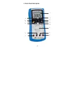
Page 42: ...4 Front Panel Description 41 1 9 11 12 10 2 3 4 8 13 7 14 5 6 ...

Page 43: ...IN HOLD Function For measuring the MIN or Max value make the following steps Press the MIN MAX button to display the max measured value MAX Symbol appears in the LCD Press MAX MIN again to display the min measured value MIN Symbol appears in the LCD Press MAX MIN again to show the present measured value MAX MIN appears in the LCD Press and hold the MAX MIN button for 1 second to leave the MIN MAX ...

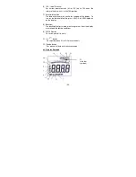
Page 44: ...eter can be activated by turning the rotary switch or pressing any button it will display the last measurement value before entering auto power off To disable the auto power off function press any one of the MIN MAX RANGE REL or RS232C buttons while turning on the meter 4 1 Description 1 Digital Display Digital readings are displayed on a 3999 count display with automatic polarity indication and d...

Page 45: ...the display To turn on the data hold feature press HOLD until HOLD appears on the display 8 Backlight The backlight helps to read measuring values from the display at unfavourable lighting conditions 9 ON OFF button To switch on or off the unit 11 button To select between AC or DC measurements 12 Range button For manual selection of measuring range 4 2 Display Symbole 44 10 all other symbols ...

Page 46: ...indicator 4 Diode test 5 Continuity test 6 Relative Mode 7 Data Hold 8 Indicator for DC voltage or current 9 Indicator for AC voltage or current The display value is the mean value 10 Symbols for resistance frequency voltage current capacitance and temperature 11 Analogue Bar Graph 12 OL Overload indication 13 computer connection 14 Auto power off 45 ...

Page 47: ...rious shock hazard 5 2 Using the stand Use your meter s stand to prop up the meter If you prop your meter on a bench top the stand helps provide a better viewing angle To use the stand as a prop just open it away from the meter and set it on a flat surface 6 How to make measurements Understanding Phantom readings In some DC and AC voltage ranges when the test leads are not connected to any circuit...

Page 48: ...ctor switch to another range It could damage the meter s internal components or injure you 6 2 Measuring DC AC Current WARNINGS Do not apply voltage directly across the terminals You must connect the meter in series with the circuit The 10A terminal is fused A severe fire hazard and short circuit danger exists if you apply a voltage with high current capability to this terminal The meter can be de...

Page 49: ...e Note If you see the meter for DC current appears or disappears This indicates the polarity of the measured current 6 3 Measuring Resistance WARNING Never connect the test leads to a source of voltage when you have the selected the OHMS function and plugged the test leads into the V Ω Hz terminal Be sure that the circuit under test has all power removed and that any associated capacitors are full...

Page 50: ...note of this value and subtract it from small resistance measurements for better accuracy 6 4 Checking diodes This function lets you check diodes and other semiconductors for opens and shorts It also lets you determine the forward voltage for diodes You can use this function when you need to match diodes 1 Set the rotary selector to the position 2 Plug the black test lead into your meter s COM ter...

Page 51: ...he black test lead is connected to the diode s cathode This meter supplies enough forward voltage to light most LED s However if the LED s forward voltage is greater than 2 0 volts the meter incorrectly indicates that the device is open 6 5 Checking Continuity Follow these steps to check a circuit s continuity 1 Set the rotary selector to o 2 Plug the black test lead into your meter s COM terminal...

Page 52: ...damage the meter s internal components or injure you Note For the most accurate measurements we strongly recommend you to use a BNC cable with ferrite core 6 7 Capacitance measurements WARNING To avoid electric shock disconnect power to the unit under test and discharge all capacitors before taking any capacitance measurements Remove the batteries and unplug the line cords 1 Set the function switc...

Page 53: ...h to the C range 2 Insert the temperature probe into the V Ω Hz terminal and COM terminal 3 Touch the Temperature probe head to the part whose temperature you wish to measure Keep the probe touching the part under test until the reading stabilizes about 30 seconds 4 Read the temperature in the display The digital reading will indicate the proper decimal point and value Warning To avoid electric sh...

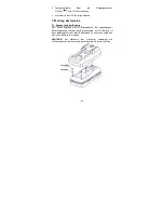
Page 54: ...nued use with a low battery will lead to abnormal readings Warning To avoid electric shock disconnect both test leads from equipment before you remove or install the battery Follow these steps to install the battery 1 Turn off the power and disconnect the two test leads 2 Remove the 3 screw to open the back cover 3 Remove the battery 4 Place the battery into the insulation capsule 5 Replace the ba...

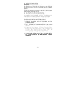
Page 55: ...tteries or accumulators built into the device itself In connection with the sale of these batteries or accumulators we are obliged under the Battery Regulations to notify our customers of the following Please dispose of old batteries at a council collection point or return them to a local shop at no cost The disposal in domestic refuse is strictly forbidden according to the Battery Regulations You...

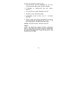
Page 56: ... test leads before removing the battery or the fuse Replace only with the same type of battery or fuse Service should be performed only by qualified personnel Caution For continued protection against fire or other hazard replace only with a fuse of the specified voltage and current ratings F1 1 A 250 V F 5 x 20 mm F2 10 A 250 V F 5 x 20 mm Follow these steps to replace the fuse 1 Turn off the mete...

Page 57: ...ase follow below procedure 1 Insert the provided CD ROM into CD ROM drive Double click the MY COMPUTER icon on the Windows Desktop Locate the CD ROM drive from the windows double click the drive letter to display the folder of P 3315 Double click P 3315 to display the contents of the folder Double click the file P3315 EXE 2 Follow the on screen installation instructions 3 The installation program ...

Page 58: ...onnect the other end of the cable to the serial or USB port of computer as show on following figure 2 Press RS 232 button to activate the interface 3 Front the Windows START menu choose PROGRAMS P 3315 Interface Program P 3315 4 Press P3315 EXE to select corresponding COM 1 2 3 4 if using RS 232 C connection or press USB Connect from menu bar when using USB connection to start the connection betwe...

Page 59: ...cal knowing Technical changing which are in the interest of progress reserved We herewith confirm that the units are calibrated by the factory according to the specifications as per the technical specifications We recommend to calibrate the unit again after 1 year PeakTech 07 2012 th PeakTech Prüf und Messtechnik GmbH Kornkamp 32 DE 22926 Ahrensburg Germany 49 0 4102 42343 44 49 0 4102 434 16 info...

Reviews: