PowerWave 2 Bus System BCMS Setup and Operation
Cntl Nr: PM375107-002
28
4.1.2
Customer Power Connections to Display Interface Board
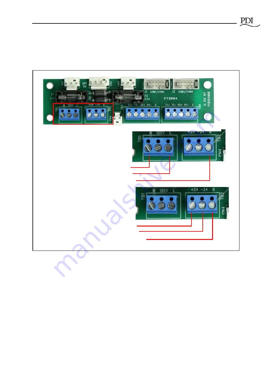
The Local Display accepts 120VAC (1P) or +24VDC power input at TB1 and TB1 on the Display Interface
Board. Connections are labeled on the board (Figure 20).
Figure 20 Customer Power Connections to Display Interface Board
4.1.3
Modbus Network Connections
Modbus RTU connections are also made to the Display Interface Board (Figure 21):
•
Upstream Modbus
connection is to Modbus master device, such as a BMS or DCIM system
•
Downstream Modbus
connection is to the Accumulator PCB in the power feed of the first
(nearest) bus run in the monitored chain.
+24VDC
•
C24VDC to TB2 pin 1.
•
Connect 24VDC return to TB2 pin 2.
•
Connect Ground to TB2 pin 3.
120VAC
•
Connect Neutral Voltage to TB1 pin 1.
•
Connect Phase Voltage to TB1 pin 3.
•
Connect Ground to TB2 pin 3.


