Brought to you by PCS Electronics, www.pcs-electronics.com
40
Limiting maximum adjustable power for driving pallets
MAX PRO 5015 (5025 and 5040 are usually too strong) has been developed as a pallet driver and it is ideal for this task. Of
course for most situations 15W will be too much and you will want to limit maximum output power of this FM transmitter
to a lower value and at the same time prevent accidental setting of higher power via LCD module. This is especially
important when you use this exciter to drive an amplifier. Most amplifiers will not appreciate over-driving the input and will
eventually be damaged by excessive power on the input. There are scenarios and ways to limit output power, they are
described below with their advantages and disadvantages. You should PERFORM THESE ADJUSTMENTS
BEFORE CONNECTING AMPLIFIER as otherwise it may be too late, a short burst of full power before you turn the
power off or adjust the trimmer may kill the amplifier. A very good design practice is also to use an attenuator (just a small
1-3dB) between exciter and amplifier, remember amplifiers input impedance can be a long way from prescribed 50 ohms
and attenuator nicely equalizes that out.
Step1 – establish needed drive power
Check the datasheet/specs of your amplifier, it will state how much drive power is needed. For the purpose of simplicity let
us assume that the datasheet asks for 3.2W of drive power. Since there is some variation from pallet to pallet and we want to
have a tiny bit of headroom also for the attenuator lets set output power to 4W.
Step2 - set maximum output power to 4W
Look for power limit jumper J12, it is located close to the telemetry connector. Set J12 to 4W, this will limit output power to
about 4W. Thanks to the new design of the MAX this output power is flat across the entire FM band, this is a
great advantage compared to our 3000+ and 4000+ series exciters.
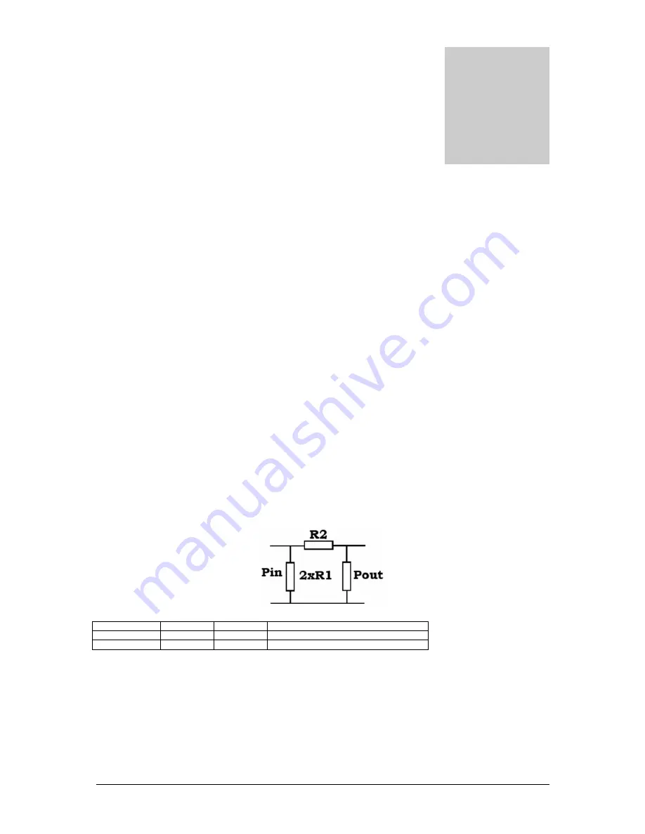
Step3 – reduce 4W down to the needed 3.5W with attenuator (optional, but recommended)
As already mentioned before a very good design practice is to use an attenuator (just a small 1-2dB) between exciter and
amplifier, remember amplifiers input impedance can be a long way from prescribed 50 ohms and attenuator nicely equalizes
that out. We are going to use such an attenuator to bring 4W down to around 3.2W.
Fig 18: Attenuator
Loss in dB
R1 ohms
R2 ohms
Input power (Pin) for 3.2W output power (Pout)
1
870
5.8
4W
2
436
11.6
5.12W
Resistor values for required attenuation
It seems 1dB will be just perfect. You can use 2x820ohm 2W resistors and 1x5.6ohm 2W resistor. Use regular carbon 2W
resistors (not! wire-wound), they will work well for this purpose at 100MHz, just keep the leads very short.
Chapter
9


