


GRL-PCIE-TX Quick Start/User Guide/MOI
Rev1.0
© PCI-SIG 2022
Version 1.0, Mar 2022. Updated 03.26.2022
Page.
15
4.2.1
Connect Equipment for System Board DUT Test
The connection diagrams below show the recommended equipment setups to perform waveform
acquisition and analysis for the PCIe System Board DUT using a GRL automation control enabled
Scope and test controller method.
4.2.1.1
Setup Using GRL-P1 Hardware Controller with PCIe Test Fixtures
The following diagrams describe how to connect the equipment if using GRL-P1 with the PCIe
Gen5 Compliance Load Board (CLB).
Note the use of GRL-P1 in the setup is optional.
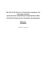
4.2.1.1.1
PCIe Gen5 System Board Connection Setup
F
IGURE
10.
C
ONCEPTUAL
PCI
E
G
EN
5
S
YSTEM
B
OARD
T
X
T
EST
S
ETUP
D
IAGRAM
U
SING
GRL-P1
1.
Insert the CLB into the designated slot on the DUT.
2.
Connect the Tx+ Data Lane from the CLB to Channel 1 of the Scope.
3.
Connect the Tx- Data Lane from the CLB to Channel 3 of the Scope.
4.
Connect the CLB Rx+ Lane to the GRL-P1 Output 1.
5.
Connect the CLB Rx- Lane to the GRL-P1 Output 2.
6.
Connect the power control adapter cable from the ATX power supply to the DUT.


