background image


©  PCE Instruments 


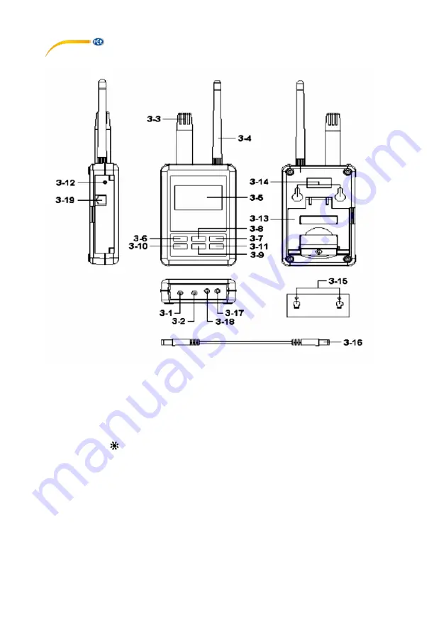
4  Device description 


Fig.1 


3.1 DC 9V power adapter input socket   


3.11 ► button


3.2 DC 9V output socket 


3.12 System reset button 

3.3 Humidity/Temp. sensor   


3.13 Stand 

3.4 Antenna and antenna socket 


3.14 Hanging holes 

3.5 Display 


3.15 Hanging unit (with sticker) 

3.6 SETUP/ENTER BUTTON  


3.16 Power interface cable/plugs 

3.7 EXIT/SHIFT ( ) button   


3.17 Isolate RS232 output socket 

3.8 ▲ button


3.18 Pt1000 input socket 

3.9 ▼ button


3.19 Network socket (RJ45) 

3.10 

 button 


Summary of Contents for PCE-HT 120

Page 1: ...hermo Hygrometer User Manual User manuals in various languages fran ais italiano espa ol portugu s nederlands t rk polski can be found by using our product search on www pce instruments com Last chang...

Page 2: ...toring to factory setting 8 5 7 AP Mode 8 5 8 Client Mode internal network 10 5 9 Client mode external network fixed IP 10 5 10 Client mode external network floating IP 11 5 11 Ethernet Mode connector...

Page 3: ...s The case should only be opened by qualified PCE Instruments personnel Never use the instrument when your hands are wet You must not make any technical changes to the device The appliance should only...

Page 4: ...emperature Measuring range 5 4 49 C 22 3 120 2 F Measuring function PT1000 Measuring range 10 70 C 14 158 F Resolution 0 1 C 0 18 F Accuracy 1 2 C 2 2 F Display LC display Interfaces RS232 SOFT LUT US...

Page 5: ...9V power input 2 DC 9V power output power supply for the connecting RS232 meter 3 Pt 1000 ohm input 4 Three RS232 inputs 5 Ethernet RJ45 input Basic settings 1 Net Mode 2 SSID 3 Password 4 IP Address...

Page 6: ...et button 3 3 Humidity Temp sensor 3 13 Stand 3 4 Antenna and antenna socket 3 14 Hanging holes 3 5 Display 3 15 Hanging unit with sticker 3 6 SETUP ENTER BUTTON 3 16 Power interface cable plugs 3 7 E...

Page 7: ...een 1 start up screen Screen 2 start up screen 5 2 Measurement and settings screens 1 Measurement screen Screen 3 temp humidity measurement Screen 4 Pt1000 measurement Screen 5 settings preview Screen...

Page 8: ...e device will be initialised over 30 sec The temp humidity measurement screen will then be displayed Screen 3 Press the SETUP ENTER button to enter the settings screen Screen 9 Use the and buttons to...

Page 9: ...the SETUP ENTER button to confirm your change o Press the button to move the selection to Gateway Gateway o The default gateway is 192 168 0 1 o Press the or button to select the value and then use t...

Page 10: ...o save the changed settings The device then needs 25 sec to reconnect Screen 7 or 8 before returning to the measurement screen Screen 5 or 6 with the factory settings restored 5 7 AP Mode First instal...

Page 11: ...re met o Alarm SMS device sends an SMS as an alarm to your smart phone when the conditions on Image 6 are met The Save button Image 5 stores the set settings and returns the device to Image 3 The Wi F...

Page 12: ...network fixed IP Simple schematic network Set the meter to Client mode with the following parameters o Net mode Client o SSID RHW 925 or used defined o IP 192 168 0 254 o Port 200 o Gateway 192 168 0...

Page 13: ...Store to learn how to set this parameter In the port forwarding settings of your IP router you can set the parameters for SSID IP address and port such as in Image 8 Apply for free transfer to www noi...

Page 14: ...t cable to input 3 19 in Fig 1 5 13 Ethernet Mode connected via wireless bridge network external network floating IP Simple schematic network Set the meter to Client mode with the following parameters...

Page 15: ...r serial port The 16 digits data stream will be displayed in the following format D15 D14 D13 D12 D11 D10 D9 D8 D7 D6 D5 D4 D3 D2 D1 D0 5 14 1 Digit chart D15 Start word D14 4 D13 1 9 D12 D11 Display...

Page 16: ...d pollutants batteries must not be disposed of as household waste They must be given to collection points designed for that purpose In order to comply with the EU directive 2012 19 EU we take our devi...

Page 17: ...583 975 114 Fax 49 0 2903 976 99 9971 Fax 44 0 2380 98703 9 Fax 39 0583 974 824 info pce instruments com info pce instruments co uk info pce italia it www pce instruments com deutsch www pce instrumen...

Reviews: