background image


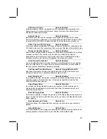
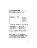
ACPI Suspend Type 

Default: S1 (POS) 

Use this item to define how your system suspends. In the default, S1(POS), the 
suspend mode is equivalent to a software power down. If you select S3 (STR), 
the suspend mode is a suspend to RAM – the system shuts down with the 
exception of a refresh current to the system memory. 

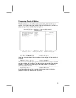
Power Management 

Default: Define 

This item acts like a master switch for the power-saving modes and hard disk 
timeouts. If this item is set to Max Saving, power-saving modes occur after a 
short timeout. If this item is set to Min Saving, power-saving modes occur after a 
longer timeout. If the item is set to User Define, you can insert your own timeouts 
for the power-saving modes.  

Video Off Method 

Default: DPMS 

This item defines how the video is powered down to save power. As a default, 
this is set to DPMS (display power management software). 

Video Off In Suspend 

Default: Yes 

This option defines if the video is powered down when the system is put into 
suspend mode. 

Suspend Type 

Default: Stop Grant 

If this item is set to the default "Stop Grant", the CPU will go into the Idle Mode.  

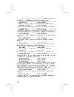
MODEM Use IRQ 

Default: 3 

If you want an incoming call on a modem to automatically resume the system 
from a power-saving mode, use this item to specify the interrupt request line 
(IRQ) that is used by the modem. You might have to connect the fax/modem to a 
mainboard Wake On Modem connector for this feature to work. 

Suspend Mode 

Default: Disabled 

If you have selected User Define for the 

Power Management

 item, you can set 

this item to a timeouts from 1 Min to 1 Hour. The system will go into the power-
saving suspend mode if the timeout passes without any system activity. 

HDD Power Down 

Default: Disable 

If you have selected User Define for the Power Management item, you can set 
this item to a selection of timeouts from 1 to 15 minutes. The hard disk drive will 
power down if the selected timeout passes without any activity on the hard disk. 

Soft-Off by PWR-BTTN 

Default: Instant-Off 

Under ACPI (Advanced Configuration and Power management Interface) you 
can create a software power down. In a software power down, the system can be 
resumed by Wake Up Alarms. This item lets you install a software power down 
that is controlled by the normal power button on your system. If the item is set to 
Instant-Off, then the power button causes a software power down. If the item is 
set to Delay 4 Sec. Then you have to hold the power button down for four 
seconds to cause a software power down. 

Wake Up by PCI Card 

Default: Disabled 

If you enable this item, it allows activity on an add-in card in one of the PCI slots 
to resume the system from a power-saving mode. 


51

Summary of Contents for M771LMR 1.x

Page 1: ...fitness for any particular purpose Further the manufacturer reserves the right to revise this publication and to make changes from time to time in the content hereof without obligation of the manufact...

Page 2: ...e separation between the equipment and the receiver Connect the equipment onto an outlet on a circuit different from that to which the receiver is connected Consult the dealer or an experienced radio...

Page 3: ...stall the Mainboard in the Case 17 Connecting Power Chassis Fans and Switches and Indicators 19 Install Other Hardware 21 Install the Processor 21 Installing a Socket 370 Processor 22 Install the Memo...

Page 4: ...n 56 Set Supervisor and User Passwords 56 Save And Exit Setup Option 57 Exit Without Saving Option 57 Chapter 4 Software 58 About the Software 58 Folders for this Mainboard 58 Running the Support CD R...

Page 5: ...ure means that you can install the mainboard with a PPGA Celeron or FC PGA Coppermine processor The KOB 810e FSFx is installed with the enhanced Intel 810e chipset The mainboard has built in 3D graphi...

Page 6: ...hat make this one of the best value mainboards on the market About the Manual The manual consists of the following chapters Introduction Use the Introduction Chapter to learn about the features of the...

Page 7: ...atic settings by making changes to jumpers on the mainboard or changing the settings in the system setup utility We strongly recommend that you do not overclock the mainboard to run processors or othe...

Page 8: ...e KOB 810e FSFx supports 66MHz PGA Celeron as well as 100 MHz and 133 MHz front side buses FC PGA Coppermine Intel s 810e Chipset This board features 810e chipsets from Intel The 810e chipset is desig...

Page 9: ...functions The CMI 8738 PCI C3DX is a two chip solution that provides an integrated audio and fax modem system Built in AGP 3D Graphics The Intel 810e chipset includes an integrated AGP controller that...

Page 10: ...game MIDI port two USB ports and audio jacks for microphone line in and line out The board has a header for the optional installation of an IR port and second serial port The board includes two PCI I...

Page 11: ...choosing a case avoiding static electricity damage and setting jumpers Preparing the Mainboard Provides a guide to the mainboard and I O port locations full details on the jumper settings and advice o...

Page 12: ...n jumper to enable keyboard power on with hot keys or password Function Jumper Cap Disable keyboard power on Short pins 1 2 Enable keyboard power on Short pins 2 3 1 2 3 JP2 JP3 Force 100 MHz front si...

Page 13: ...s and indicators on your system case Function Pins Speaker 1 3 5 7 Power Indicator 2 4 6 Keylock 8 10 Green Indicator 13 14 Hard Disk Indicator 15 16 Reset Switch 17 18 Suspend Switch 19 20 Power Swit...

Page 14: ...Leave all components inside their static proof bags until they are required for the installation procedure Handle all circuit boards and electronic components carefully Hold boards by the edges only...

Page 15: ...the pins are OPEN This illustration shows a 2 pin jumper When the jumper cap is placed on both pins the jumper is SHORT If you remove the jumper cap or place the jumper cap on just one pin the jumper...

Page 16: ...g illustration and key to identify the components on your mainboard JHD1 CASFAN1 CPUFAN1 DIMM1 DIMM2 JP2 JP4 FDD1 IDE2 IDE1 PANEL1 SIR1 WOM1 WOL1 JP1 J1 FP1 CD2 TV Out LCD Panel Riser Slot CD1 Socket...

Page 17: ...ASFAN1 Power connector for case cooling fan CPUFAN1 Power connector for CPU cooling fan MODEM2 Connector for modem DAA module CD1 Audio connector for CD ROM DVD drive CD2 Auxiliary audio connector for...

Page 18: ...t for pointing device upper port PS 2 port for keyboard lower port LPT1 External parallel port JS Upper External game MIDI port JS Lower Audio jacks for from left to right line out line in microphone...

Page 19: ...memory turn off the system disconnect the power cable from the mainboard and short the appropriate pins for a few seconds Function Jumper Cap Normal Operation Short pins 1 2 Clear CMOS Short pins 2 3...

Page 20: ...bus 1 2 3 JP3 Function Jumper Cap Normal operation Short pins 1 2 Force 100 MHz FSB Short pins 2 3 JP4 Force 133 MHz Front Side Bus Jumper Use this 3 pin jumper to disable the automatic detection of t...

Page 21: ...the mounting brackets and driving screws through the mainboard into the mounting brackets Most cases have a choice of I O templates in the rear panel Make sure that the I O template in the case match...

Page 22: ...The illustration below shows the mainboard installing into a tower type case Power Supply Unit Drive Cage Expansion Slots I O Template 18...

Page 23: ...dicators to the PANEL connector and the J2 LED connector on the mainboard Finally connect the case open detection alarm to the J1 connector on the mainboard J2 PANEL1 CPUFAN1 J1 ATX1 CASFAN1 Power Con...

Page 24: ...al color LED connector Panel Connector The mainboard PANEL connector has a standard set of switch and indicator connectors that are commonly found on ATX system cases Use the illustration below to mak...

Page 25: ...acturers may release socket 370 processors in the future Intel have plans to release a more powerful socket 370 processor Ask your board vendor for an up to date list of processors that are supported...

Page 26: ...on the socket 370 and the pin 1 corner on the processor The socket pin 1 corner is adjacent to the handle of the locking lever The processor pin 1 corner is beveled 4 Matching the pin 1 corners drop...

Page 27: ...ver the correct clock speed and the correct system bus for the kind of processor that you have installed You can do this by using the system setup utility The first time you start the system immediate...

Page 28: ...se to install the module Each model can be installed with from 8 MB to 256 MB of memory so total memory capacity is 512 MB The mainboard supports memory chips that have EC Error Correction or ECC Erro...

Page 29: ...channel interface IDE1 and a secondary IDE interface IDE2 The mainboard ships with one IDE ribbon cable which supports one or two IDE devices All IDE devices have jumpers or switches that can be used...

Page 30: ...hard disk drive 5 When you first start up your system go immediately to the setup utility and use the IDE Hard Disk Auto Detect feature to configure the IDE devices that you have installed See Chapte...

Page 31: ...Hard Disk Auto Detect feature to configure the IDE devices that you have installed See Chapter 3 for more information Power connector CD ROM DVD drive Hard disk drive CD1 CD2 IDE1 IDE2 IDE ribbon cab...

Page 32: ...ure that you have the pin 1 side of the cable matched with the pin 1 side of the connector 3 Plug a power cable from the case power supply unit into the power connector on the back edge of the diskett...

Page 33: ...card check the documentation for the card carefully If the card is not Plug and Play you may have to manually configure the card before installation 2 Select which expansion slot you are going to use...

Page 34: ...ard has two features that can be used if you have installed either a fax modem card or a network adapter card WOL1 Wake on LAN If you have installed a network adapter LAN adapter you can use the cable...

Page 35: ...ically resume the system You must enable this item using the Power Management page of the setup utility See Chapter three for more information Install Options and Extension Brackets This mainboard has...

Page 36: ...slot blanking plate from the system chassis that is adjacent to the fax modem connector 3 Install the fax modem card on to the MODEM2 connector as shown below The RJ11 Line and Telephone sockets on t...

Page 37: ...the cable secure the optional IR port to the appropriate place on your system case Note An IR port may use some of the resources required by a second serial port or a fax modem card If you have more...

Page 38: ...of these items installed you may not be able to use them at the same time You can use the Peripherals page of the setup utility to switch resources between an IR port and a second serial port See Cha...

Page 39: ...The upper 15 pin port J2 is a game MIDI port You can use this port to connect a joystick or a MIDI device to your system 4 The lower part of J2 is three audio jacks The left side jack is for a stereo...

Page 40: ...GA Blue Audio line in Light blue Audio line out Lime Digital monitor flat panel White IEEE 1394 Grey Microphone Pink MIDI Game Gold Parallel Burgundy PS 2 compatible keyboard Purple PS 2 compatible mo...

Page 41: ...you to make changes to the setup utility This happens when the system finds an error during the POST Power On Self Test that it carries out at start up Starting the Setup Utility You can only start t...

Page 42: ...ing the Escape key You can save the current selections and exit the utility by pressing the F10 key When you are in one of the options that displays a dialog box you can return to the main menu by pre...

Page 43: ...for the present 3 Your computer must be running in a real mode DOS environment not the DOS window of Windows NT or Windows 95 98 We recommend that you create a new formatted DOS system floppy diskette...

Page 44: ...S Features Option This option displays a table of items which defines basic information about your system Date and Time The Date and Time items show the current date and time held by your computer If...

Page 45: ...fines some special ways that can be used to access IDE hard disks such as LBA Large Block Addressing Leave this value at Auto and the system will automatically decide the fastest way to access the har...

Page 46: ...ifications to most of these items without introducing fatal errors to your system Note that the page has a scroll bar to scroll down to more items Anti Virus Protection Default Disabled When this item...

Page 47: ...ave your system start up a little faster You might like to enable this item after you are confident that your system hardware is operating smoothly First Second Third Boot Device Default Floppy HDD 0...

Page 48: ...ypematic Rate Setting is enabled you can use this item to define how many milliseconds must elapse before a held down key begins generating repeat characters Security Option Default Setup If you have...

Page 49: ...e has a scroll bar to scroll down to more items SDRAM CAS Latency Time Default 3 SDRAM Cycle Time Tras Trc Default 6 8 SDRAM RAS to CAS Delay Default 3 SDRAM RAS Precharge Time Default 3 These four it...

Page 50: ...de compliance with PCI Ver 2 1 specifications We recommend that you leave this item at the default value On Chip Video Window Size Default 64 MB This item defines the size of the aperture if you use a...

Page 51: ...Slave PIO Default Auto Each IDE channel supports a master device and a slave device These four items let you assign which kind of PIO Programmed Input Output is used by IDE devices You can choose Aut...

Page 52: ...is function to the mainboard AC97 Audio Default Auto We recommend that you set this item to Auto when you use AMR card AC97 Modem Default Auto We recommend that you set this item to Auto when you use...

Page 53: ...O address and an Interrupt Request Line IRQ Parallel Port Mode Default SPP ECP Mode Use DMA Default 3 This item defines the operation of the parallel port As a default it is set to SPP standard parall...

Page 54: ...rolled by timeouts If the system is inactive for a time the timeouts begin counting If the inactivity continues so that the timeout period elapses the system enters a power saving mode If any item in...

Page 55: ...item to specify the interrupt request line IRQ that is used by the modem You might have to connect the fax modem to a mainboard Wake On Modem connector for this feature to work Suspend Mode Default Di...

Page 56: ...CPU throttling is initiated by excess heat Resume by Alarm Default Disabled If this item is Enabled it allows you to set a date and time alarm that will automatically resume the system from a software...

Page 57: ...uired If you cannot get a legacy ISA Industry Standard Architecture expansion card to work properly you might be able to solve the problem by changing this item to Manual and then opening up the IRQ R...

Page 58: ...s not require palette snooping so you must leave this item disabled PCI Health Status Option On mainboards which support hardware monitoring this item lets you monitor the parameters for critical volt...

Page 59: ...ock signal of free DIMM and PCI slots CPU Internal Core Speed Default 233 MHz Use this item to automatically set up the mainboard for the kind of processor that you have installed Set this item to the...

Page 60: ...you only want to install a fail safe defaults for a specific option select and display that option and then press the F6 key Load Optimized Defaults Option This option opens dialog box that lets you...

Page 61: ...er or just press Enter if you are deleting a password that is already installed 5 If you typed the password correctly the password will be installed Save And Exit Setup Option Highlight this item and...

Page 62: ...e KOB 810e FSFx folder Note Never try to install software from a folder that is not specified for use with your mainboard Folders for this Mainboard For this board you can install software from the fo...

Page 63: ...Folder You can use the software in the following sub folders MONITOR Hardware monitoring software for Windows 95 98 and Windows NT4 0 5 0 ACPI AUDIO MODEM VGA WIN9x Inf These folders are empty A readm...

Page 64: ...ash Memory Utility This utility lets you erase the system BIOS stored on a Flash Memory chip on the mainboard and lets you copy an updated BIOS to the chip Take care how you use this program If you er...

Page 65: ...98 Installation Please specify the path to the CD ROM CMI8X38 AUDIO_ITE_GAME W95 98 DRV when your system detects the installed audio system To install the audio applications log on to the W95 98 fold...

Page 66: ...tes Keyboard CD ROM Mouse Follow the instructions contained in the documentation files in these folders Intel Folder Installation Notes I810_ACPI This folder has a patch that allows a Windows 95 98 sy...

Page 67: ...nstallation Notes Most of the sub folders in this folder are empty with a short README file giving directions to alternate folders for the appropriate software Two folders contain software that you ca...

Page 68: ...2 Enable keyboard power on Short pins 2 3 1 2 3 JP2 JP3 Force 100 MHz front side bus jumper Use this jumper to disable the automatic detection of the correct front side bus and force the system to run...

Page 69: ...and indicators on your system case Function Pins Speaker 1 3 5 7 Power Indicator 2 4 6 Keylock 8 10 Green Indicator 13 14 Hard Disk Indicator 15 16 Reset Switch 17 18 Suspend Switch 19 20 Power Switc...

Reviews: