PCB Piezotronics M1204-13A Installation And Operating Manual Download Page 11


PCB Load & Torque, Inc.   

 Toll-Free in USA 866-684-7107   

 716-684-0001   

 www.pcbloadtorque.com


GENERAL PURPOSE LOW PROFILE LOAD CELL OPERATION MANUAL 


5


5.0 ELECTRICAL INSTALLATION 


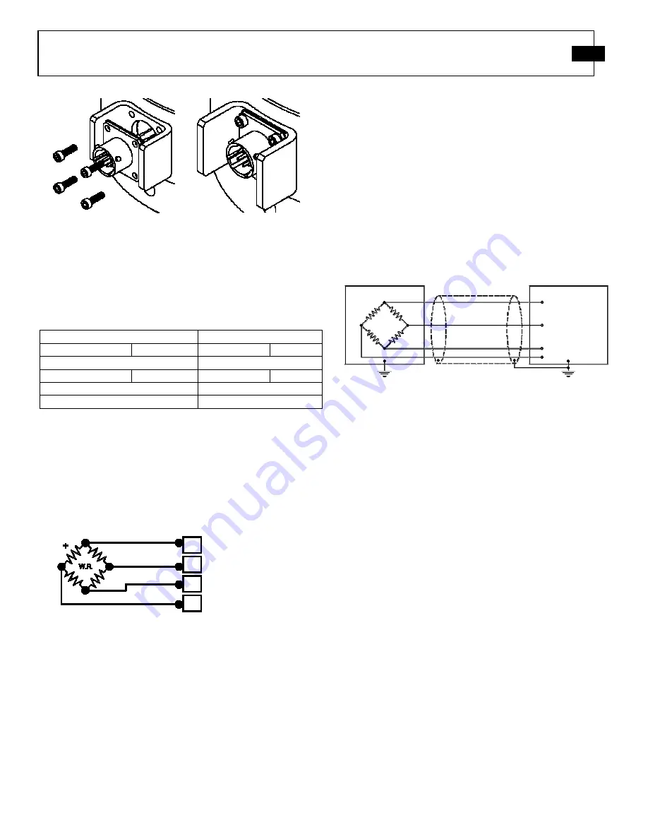
5.1 Electrical Drawing / Western Regional Std. 

All  load  cells  are  wired  following  the  Western  Region 
Standard.    All  models  utilize  strain  gages  configured  into  a 
Wheatstone  Bridge  Circuit  to  produce  the  primary  sensing 
element.  The  four-arm  Wheatstone  bridge  configuration  is 
shown below in Figure 11. 


The  gages  are  bonded  to  the  load  cell's  structure. 
Typically,  a  regulated  DC  or  AC  excitation  is  applied 
between A and D of the bridge. When a force is applied to 
the  load cell,  the Wheatstone  bridge  becomes  unbalanced, 
causing  an  output  voltage  between  B  and  C,  which  is 
proportional to the applied load.  This configuration allows 
for  temperature  and  pressure  compensation,  as  well  as 
cancellation  of  signals  caused  by  forces  not  directly 
applied to the axis of the applied load. Output is typically 
expressed in units of mV/V of excitation. 
 

5.2 Cable & Grounding Considerations 

Proper  grounding  and  shielding  is  required  to  prevent 
electrical  noise  in  strain  gage  load  cell  measuring  systems.  
The cable must be shielded twisted pairs with a drain wire. 
 
Cable shields must be grounded only at one end, for example, 
on  the  instrument  or  control  system  ground.    The  load  cell 
case is grounded by mechanical attachment to the structure to 
which it is mounted. 
 
The  instrument  or  control  system  is  grounded  through  its 
power cord.  Ground loops and measuring system wiring may 
result in unstable or noisy signals. 


A  simple  test  with  a  voltmeter  connected  between  the  power 
cord  ground  and  the  structure  on  which  the  load  cell  is 
mounted  can  confirm  that  the  structure  has  been  properly 
grounded.  If the power cord ground and structure ground are 
not  at  the  same  potential,  it  may  be  necessary  to  provide  a 
secure  structure  ground,  perhaps  by  driving  a  copper  rod  and 
attaching a ground strap. 


6.0 CALIBRATION 

 
Every  general  purpose  low  profile  load  cell  purchased  from 
PCB Load & Torque, Inc. has been fully calibrated in tension 
and compression per ISO/IEC 17025 procedures, and meets all 
published  specifications.    Each  load  cell  will  come  with  a 
calibration  certificate  designated  with  matching  model  and 
serial  numbers.  PCB  Load  &  Torque  also  offers  calibration 
services on an on-going basis. 
 

6.1 Calibration Certificate Description 

Calibration reports supplied with PCB Load & Torque general 
purpose low profile load cells contain valuable information to 
assist  the  customer  in  use  of  the  equipment.  A  separate 
calibration  report  is  provided  for  tension  and  compression 
calibrations 

on 

each 

bridge. 

Calibration 

procedures, 

equipment, and reports comply with ISO/IEC 17025. 

Load Cell Receptacle “A”: 

PT02E-10-6P 

Mating Connector: 

PT06A-10-6S 

PCB Item No: 

181-012A 

Load Cell Receptacle “B”: 

PC04E-10-6P 

Mating Connector: 

PC06A-10-6S 

PCB Item No: 

182-025A 

Load Cell Receptacle “C”: 

PT02E-12-8P 

Load Cell Receptacle “D”: 

PC01E-12-8P 


Table 6


– Electrical Connection Options 

Figure 12


- Grounding 


Test Rig Ground 

Power Supply 

Instrument Ground 

Cable Shielding 

Load Cell 


- Signal White 

- Excitation Black 

+ Excitation Red 

+ Signal Green 

Figure 11 - Western Regional Strain Gage Committee Wiring Code 

Figure 9 - Attach the Connector 

Protector (54823-02) using #4-40 x 

3/8” Socket Head Cap Screws 

Figure 10 - Fully Assembled 


Summary of Contents for M1204-13A

Page 1: ...oad cell Installation and Operating Manual For assistance with the operation of this product contact PCB Piezotronics Inc Toll free 800 828 8840 24 hour SensorLine 716 684 0001 Fax 716 684 0987 E mail...

Page 2: ...repair User servicing or repair is not recommended and if attempted may void the factory warranty Calibration Routine calibration of sensors and associated instrumentation is recommended as this helps...

Page 3: ...ry customer service representative Warranty All equipment and repair services provided by PCB Piezotronics Inc are covered by a limited warranty against defective material and workmanship for a period...

Page 4: ...isclosure Table Pb Hg Cd Cr VI PBB PBDE O O O O O O PCB X O O O O O O O O O O O X O O O O O O O O O O O O O O O O O O O O O O O O O X O O O O O O O O O X O O O O O O O O O O O X O O O O O X O O O O O...

Page 5: ...e O O X O O O Wires O O O O O O Cables X O O O O O Plastic O O O O O O Solder X O O O O O Copper Alloy Brass X O O O O O This table is prepared in accordance with the provisions of SJ T 11364 O Indica...

Page 6: ...nted Steel Sensing Element Strain Gage Strain Gage Mounting Torque 1400 lbf in 158 Nm Deflection at Full Scale Capacity 0 002 in 0 05 mm Electrical Connector PT02E 10 6P PT02E 10 6P All specifications...

Page 7: ...4 5 0 ELECTRICAL INSTALLATION 5 5 1 Electrical Drawing Western Regional Std 5 5 2 Cable Grounding Considerations 5 6 0 CALIBRATION 5 6 1 Calibration Certificate Description 5 6 1 1 Measured Output 6...

Page 8: ...evaluated for potential failure modes of the fixtures It is important to use threaded fasteners properly when assembling test fixtures used with the load cells Fixtures with inadequately designed bol...

Page 9: ...modified 4 2 Mounting Load Cell to a Standard Base or Custom Fixture If the load cell is to be mounted to a custom base or fixture it is necessary to consider the following 1 The thickness of the new...

Page 10: ...f Connector Protector 1 Remove the 4 40 x 1 4 button head cap screws from the connector using a 1 16 hex wrench as shown in Figure 7 2 Carefully pull the connector from the load cell Take care to not...

Page 11: ...A simple test with a voltmeter connected between the power cord ground and the structure on which the load cell is mounted can confirm that the structure has been properly grounded If the power cord g...

Page 12: ...into the load cell structure The strain gage bridges on general purpose low profile load cells are adjusted such that the error due to eccentric loading is less than 0 25 per inch of offset for 1200 s...

Page 13: ...s on the load cell If possible remove all loads 2 Power up the host signal conditioner and connect it to the load cell via appropriate cable and allow for a 30 minute warm up 3 Set the load indicator...

Page 14: ...e load cell is mounted on 5 Check the signal conditioning electronics for proper setup 6 Check the insulation resistance of shielded conductors for short circuits 7 Check isolation resistance load cel...

Page 15: ...der Please request a return material authorization RMA before sending a load cell back to the factory for any reason For calibration services if possible a copy of the purchase order covering the requ...

Reviews: