


22
•
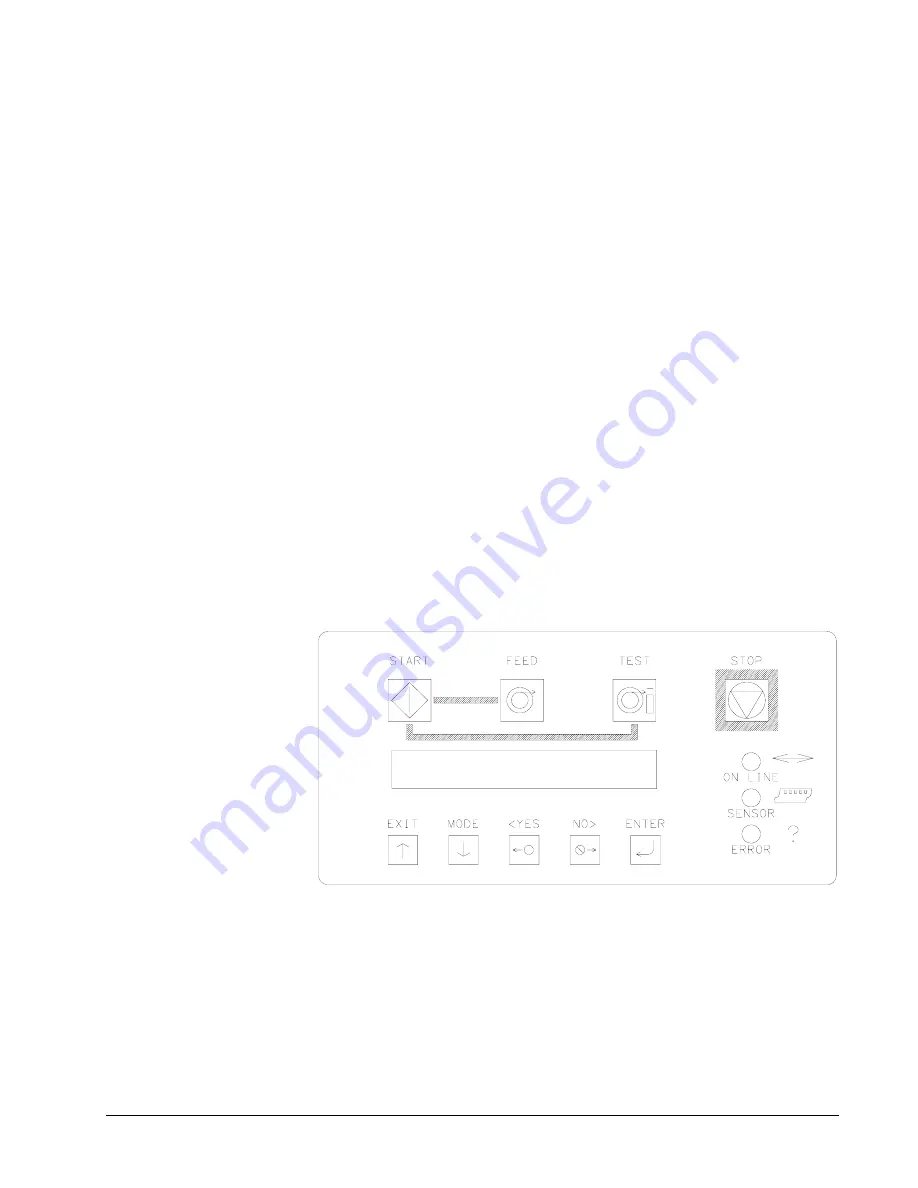
Control Panel Operation
ORANGE
- System is operational
- Ready for batches to be downloaded
GREEN
- Batches to print, ready to start
Sensor
GREEN = "C" SENSOR
- Printer is stopped, - light is on, - sensor is setting over a web sensor
mark
- Flashing light while the printer is running, - the sensor is in-line with
the registration HOLES
ORANGE = REFLECTIVE SENSOR
- Flashing light while the printer is running, - the sensor is in-line with
the registration PRINTED MARKS
Error
ORANGE
- System inter-lock triggered, display for error LCD Display
The LCD display is a 2 line, 24 character, with back lighting feature for easy
readability. The first line of the display, in most cases, will be a prompt or question -
the second line is the response.
Summary of Contents for 676
Page 2: ...Users Manual Model 676 This page intentionally blank ...
Page 85: ...Users Manual Model 676 Mechanical Assembly Drawings 85 Mechanical Assembly Drawings ...
Page 86: ...86 Mechanical Assembly Drawings Users Manual Model 676 Unwind Assembly Drawing ...
Page 88: ...88 Mechanical Assembly Drawings Users Manual Model 676 Web Guide Light Bar Assembly Drawing ...
Page 92: ...92 Mechanical Assembly Drawings Users Manual Model 676 Top Printhead Assembly Drawing ...
Page 94: ...94 Mechanical Assembly Drawings Users Manual Model 676 Ink Save Printhead Assembly Drawing ...
Page 96: ...96 Mechanical Assembly Drawings Users Manual Model 676 Bottom Printhead Assembly Drawing ...
Page 98: ...98 Mechanical Assembly Drawings Users Manual Model 676 Ink Unwind Assembly Drawing ...
Page 100: ...100 Mechanical Assembly Drawings Users Manual Model 676 Ink Rewind Assembly Drawing ...
Page 108: ...108 Mechanical Assembly Drawings Users Manual Model 676 Stacker Assembly Drawing Part 1 ...
Page 110: ...110 Mechanical Assembly Drawings Users Manual Model 676 Stacker Assembly Drawing Part 2 ...
Page 112: ...112 Mechanical Assembly Drawings Users Manual Model 676 Rewind Assembly Drawing ...
Page 114: ......
Page 116: ...116 Mechanical Assembly Drawings Users Manual Model 676 Optional 4 1 4 Pick up Assembly ...
Page 118: ...118 Mechanical Assembly Drawings Users Manual Model 676 Optional 4 1 4 Stacker Assembly ...


