background image

SmartNode 10100A Series Quick Start Guide

7

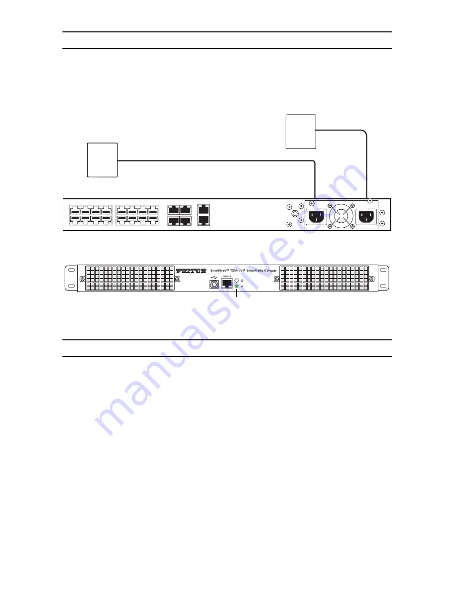
6.0  Connecting to the power source

   1.

Connect AC power cables between the AC connectors of the SN10100A and the 
two independent power sources (see 

figure 5

).

   2.

Verify that the Power LED on the front panel (see 

figure 6

) is a solid green.

Figure 5. 

Connecting the power source

Figure 6. 

Power LED location

7.0  Connecting to the Control host

   1.

Connect to the Control host through the console serial port (see 

7.1 “Connecting 

the console serial port” 

on page 8) OR the Ethernet management interface (see 

7.2 “Connecting the Ethernet management interface” 

on page 8). 

The IP address of the management port is 

192.168.200.10/24

. If it is not possible 

to connect to the management port via IP, use the serial cable to connect to the 
SmartNode Control host for the first time. 

   2.

Default HOSTNAME is the Control host serial number, which can be found in the 
“Important Notice” sheet included with your shipment. 

   3.

Refer to the "Important Notice" sheet for the username and password to log onto 
the SmartMedia WebPortal. Navigate to: HTTP://HOSTNAME:12358, to configure 
the SmartNode unit. (username/password: root/root) 

AC

Powe

r

S

o

ur

ce 1

AC

Powe

r

S

o

ur

ce 2

15

14

13

12

10 11

8

9

3

2

0

7

6

5

4

1

MGMT0

MGMT1

ETH0

ETH1

VOIP0

VOIP1

Powe

r

 LED

Summary of Contents for SmartNode SN10100A Series

Page 1: ...Start Guide Important This is a Class A device and is not intended for use in a residential environment Part Number 07MSN10100 QS Rev C Revised August 24 2018 Sales Office 1 301 975 1000 Technical Sup...

Page 2: ...are rated for proper voltage current anticipated temperature flamma bility and mechanical serviceability WAN LAN PSTN ports connections may have hazardous volt ages present regardless of whether the d...

Page 3: ...r Entflammbarkeit und mechanische Wartbarkeit geeignet sind WAN LAN u PSTN Ports Anschl sse k nnen unter gef hrlicher Spannung stehen unabh ngig davon ob das Ger t ein oder ausges chaltet ist PSTN bez...

Page 4: ...packing slip One SmartNode SN10100A Series Quick Start Guide One SmartNode SN10100A Important Notice sheet with unique information for your specific unit 2 0 Installing the rack hardware 1 Install ra...

Page 5: ...Chassis As a standard safety practice the chassis of the SN10100A series gateway must be properly grounded to protect against any contact with an electrical fault condition It is recommended that the...

Page 6: ...nd lug of the SN10100 series gate way See figure 4 2 Connect the other end of the ground wire to a ground bar of the equipment rack If the SN10100 series gateway is not installed in an equipment rack...

Page 7: ...terface see 7 2 Connecting the Ethernet management interface on page 8 The IP address of the management port is 192 168 200 10 24 If it is not possible to connect to the management port via IP use the...

Page 8: ...e serial port 7 2 Connecting the Ethernet management interface 1 Connect the supplied CAT5 Ethernet cable to the management port labeled MGMT0 on the rear of the SmartNode 10100A see figure 8 on page...

Page 9: ...c credentials included on the Important Notice that shipped with your unit If you do not have the Important Notice sheet contact support patton com 8 2 Accessing the SmartNode via the Ethernet Managem...

Page 10: ...t Management port on page 9 9 1 Connecting to the web server Using a web browser connect to the Web Portal by typing the following in your address bar http DEVICE HOST NAME 12358 or alternately http D...

Page 11: ...tee that interference will not occur in a particular installation If the equipment causes interference to radio or television reception which can be deter mined by disconnecting the cables try to corr...

Page 12: ...41 0 31 985 25 55 Switzerland Monday Friday 9 00 am to 5 30 pm CET 08 00 to 16 30 UTC GMT Fax 1 253 663 5693 USA or 41 0 31 985 25 26 Switzerland Copyright statement Copyright 2013 2018 Patton Electro...

Reviews: