background image

Save Changes

Select Save Changes to save any modifications in the previous sec-

tions. Changes not saved will be lost when the Model 2530 is powered
OFF.

Logoff

Select Logoff to exit the Software Configuration. After selecting

Logoff, the 2530 will re-display the login screen.

19

4.0  INSTALLATION

After the Model 2530 has been properly configured it may be con-

nected to the serial port, twisted pair interface, and to the power
source. This section tells you how to make these connections.

4.1   CONNECTING THE SERIAL PORT 

The serial port interface on the Model 2530 uses interchangeable

QuikConnect™ Modules to connect to your DTE. Each
QuikConnect™ Module has a 50-pin card edge connector on one side
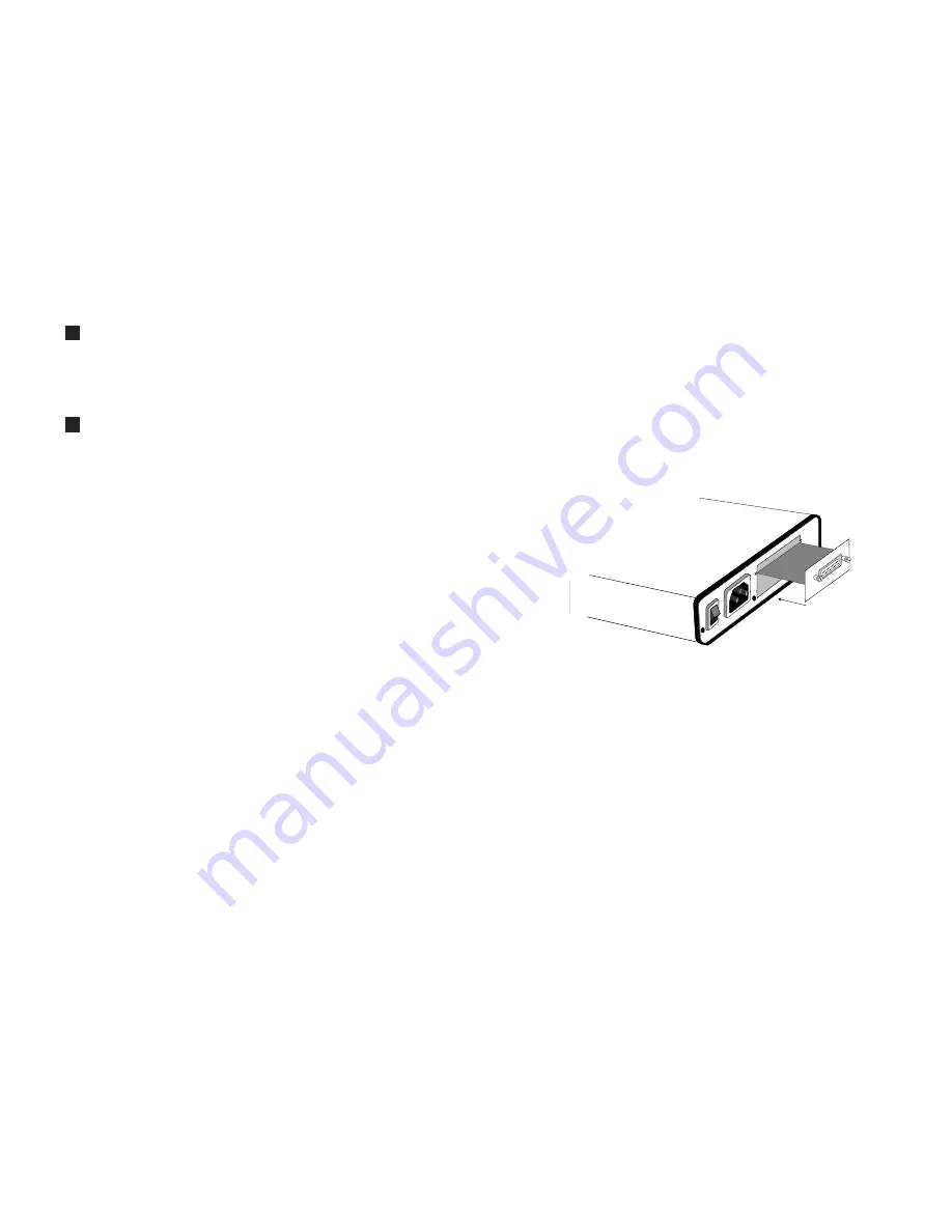
and a serial port interface on the other. Figure 3  below shows how a
QuikConnect™ Module plugs into the back of the Model 2530.

4.1.1   Changing 

QuikConnect™ Modules

When you purchase a Model 2530, it should be shipped to you

with the appropriate 

QuikConnect™ Module already installed. If you

need to install a different 

QuikConnect™ Module, follow these steps:

Removing the Existing 

QuikConnect™ Module 

1)  Turn the power switch off. Leave the power cord plugged into a

grounded outlet to keep the unit grounded.

2)  Loosen the two thumbscrews on the module by turning them

counter-clockwise.

3)  Grasp the two thumbscrews and gently pull the module from

the unit. Apply equal force to the thumbscrews to keep the
module straight during the removal process.

20

g

h

0 OFF

1 ON

Line

Interface Port

Figure 3. Installation of Model 2530 Plug-in Serial Interface Module

Summary of Contents for DigiLink-V 2530

Page 1: ...MODEL 2530 DigiLink V All Rate DDS CSU DSU SALES OFFICE 301 975 1000 TECHNICAL SUPPORT 301 975 1007 http www patton com Part 07M2530 B Doc 099101UB Revised 02 09 99 C E R T I F I E D An ISO 9001 Certi...

Page 2: ...uct These damages include but are not limited to the following lost profits lost savings and incidental or consequen tial damages arising from the use of or inability to use this product Patton Electr...

Page 3: ...of this Patton Electronics product This product has been thoroughly inspected and tested and is warrant ed for One Year parts and labor If any questions or problems arise during installation or use of...

Page 4: ...itches S1 1 and S1 2 to configure the DTE rate of the Model 2530 This rate represents the synchronous or asynchronous rate at which the DTE must connect to Model 2530 s QuikConnect interface S1 1 S1 2...

Page 5: ...1 start bit 8 data bits 1 stop bit 0 parity bits 10 bits 7 Switch S1 8 Extended Signaling Rate Use S1 8 to configure the frequency tolerence the Model 2530 looks for in asynchronous data rates i e the...

Page 6: ...lways ON Off Follows The RTS input controls the DTE Signal transmitter NOTE At 64 kbps Force RTS is always on 9 Switch S2 7 Data Set Ready During LOCAL Loopback Test Use Switch S2 7 to control the beh...

Page 7: ...able or disable the front panel switches S3 3 Activation Description Off Enabled Front panel switches may be used to activate terminate diagnostics On Disabled Front panel switches will have no effect...

Page 8: ...tial login pass word is PATTON NOTE We recommend that you change this password after the initial login 7 The 2530 will then display the MAIN MENU screen 13 3 2 1 Introduction to MAIN MENU The MAIN MEN...

Page 9: ...3 1 to review the hard ware switch definitions To modify any of the parameters listed above 1 Key the highlighted letter that corresponds to a menu selection 2 Press Space Bar until the desired value...

Page 10: ...P Switch 3 4 is ON 1 Key the highlighted letter that corresponds to a menu selection 2 Press Space Bar until the desired value is highlighted 3 Press Enter CR to select the desired value Change Passwo...

Page 11: ...ge connector on one side and a serial port interface on the other Figure 3 below shows how a QuikConnect Module plugs into the back of the Model 2530 4 1 1 Changing QuikConnect Modules When you purcha...

Page 12: ...his cable should be of the shortest possible length we recommend 6 feet or less When purchasing or constructing a null modem interface cable use the pin diagrams in Appendix D as a guide NOTE Pin out...

Page 13: ...features twenty four 24 front panel LEDs that monitor the line rate power the DTE signals the network connection and test modes Figure 5 below shows the front panel location of each LED Following Figu...

Page 14: ...ppendix D 25 2 Verify that the data terminal equipment is operating properly and can be used for a test 3 Perform a V 52 BER bit error rate test as described in Section 5 3 3 If the BER test equipment...

Page 15: ...d the communication link s are functioning properly 511 Initiates a built in 511 bit pseudo random pattern generator and detector 511 with Errors Initiates a built in 511 bit pseudo random pattern gen...

Page 16: ...F 0 50 C Altitude 0 15 000 feet Humidity 5 to 95 noncondensing Dimensions 7 3 x 6 6 x 1 62 185mm x 168mm x 41mm Weight 2 01 lbs 1 0kg Approvals FCC Part 68 FCC Part 15 UL and cUL Approvals Surge Prot...

Page 17: ...19 RTS Request to Send 20 DTR Data Terminal Ready 21 DL Remote Digital Loop 22 DSR Data Set Ready 23 DTR Data Terminal Ready B 24 XTC External Transmit Clock 25 TM Test Mode 31 APPENDIX C PATTON MODEL...

Page 18: ...eive Data A 5 I Indication A 6 S Signal Element iming A 8 SGND Signal Ground 9 T Transmit Data B 10 C Control B 11 R Receive Data B 12 I Indication B 13 S Signal Element Timing B 33 APPENDIX D PATTON...

Reviews: