background image

Installing the New 

QuikConnect™ Module 

1)  Make sure the power switch is off. Leave the power cord

plugged into a grounded outlet to keep the unit grounded.

2)  Hold the module with the faceplate toward you and align the

module with the guide slots in the rear panel of the Model
2530.

3) While keeping the module’s faceplate parallel with the Model

2530 rear panel, slide the module straight in–so that the card
edge contacts line up with the socket inside the chassis.

NOTE: The card-edge connector should meet the socket when
it is almost all the way into the chassis. If you encounter much
resistance, remove the module and repeat steps 2 & 3.

4) With the card edge contacts aligned with the socket, firmly seat

the module by using your thumbs to apply pressure directly to
the right and left edges of the module faceplate. Applying mod-
erate and 

even pressure should be sufficient to seat the mod-

ule. You should hear it “click” into place.

5) To secure the module in place, push the thumbscrews into the

chassis and turn the screws clockwise to tighten.

4.1.2   Connection to a “DTE” Device 

The serial port on most 

QuikConnect™ interface modules (all

except the X.21 module) is hard-wired as a DCE. Therefore these
modules “want” to plug into a DTE such as a terminal, PC or host.
When making the connection to your DTE device, use a straight
through 
cable of the shortest possible length—we recommend 6 feet
or less. When purchasing or constructing an interface cable, please
refer to the pin diagrams in Appendix C as a guide.

4.1.3   Connection to a “DCE” Device

If the Model 2530’s 

QuikConnect™ interface module is hard-wired

as a DCE (all except the X.21 module), you must use a 

null modem

cable when connecting to a modem, multiplexer or other DCE device.
This cable should be of the shortest possible length—we recommend 6
feet or less. When purchasing or constructing a null modem interface
cable, use the pin diagrams in Appendix D as a guide.

NOTE: Pin-out requirements for null modem applications vary 
widely between manufacturers. If you have any questions about a 
specific application, contact Patton Technical Support.

21

4.1.4   Configuring the X.21 

QuikConnect™ Module 

The serial port on the X.21 

QuikConnect™ Module is default wired

as a DCE, but may be switched to a DTE. This is done by reversing
the orientation of the DCE/DTE strap, as described below:

To reverse DCE/DTE orientation, remove the module according to

the instructions in Section 4.1.1. The DCE/DTE strap is located on the
bottom side of the module’s PC board. The arrows on the top of the
strap indicate the configuration of the X.21 port (for example, if the
DCE arrows are pointing toward the DB-15 connector, the X.21 port is
wired as a DCE). Reverse the DCE/DTE orientation by pulling the
strap out of its socket, rotating it 180

º

º, then plugging the strap back into

the socket. You will see that the DCE/DTE arrows now point in the
opposite directions, showing the new configuration of the X.21 port.
Re-install the module according to the instructions in Section 4.1.1.

4.2  CONNECTING THE TWISTED PAIR INTERFACE

The Network Interface is an 8 position modular connector. Connect

this port to the RJ-48S jack provided by the digital data service
provider. If the Model 2500 Series is being used for private short haul
communication, the twisted pair cable will connect to this port. See
Appendix C for the pin assignments of this connector.

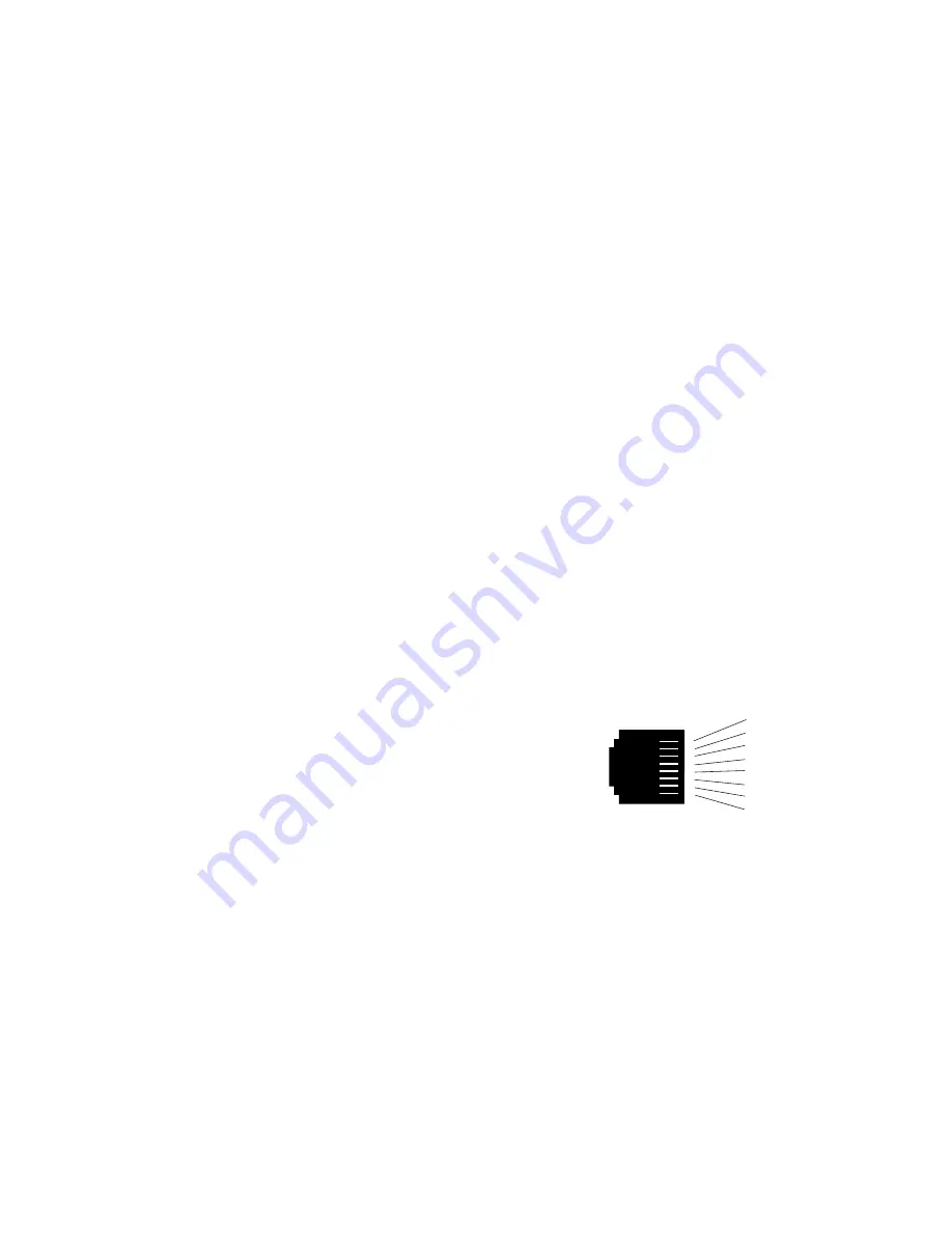
The RJ-48S connector on the Model 2530’s twisted pair interface is
pre-wired for a standard TELCO wiring environment. The signal/pin
relationships are shown in Figure 4 below.

22

Figure  4. Model 2530 twisted pair line interface.

1 (TX+)
2 (TX-)
3 (N/C)
4 (N/C)
5 (N/C)
6 (N/C)
7 (RX+)
8 (RX-)


Summary of Contents for DigiLink-V 2530

Page 1: ...MODEL 2530 DigiLink V All Rate DDS CSU DSU SALES OFFICE 301 975 1000 TECHNICAL SUPPORT 301 975 1007 http www patton com Part 07M2530 B Doc 099101UB Revised 02 09 99 C E R T I F I E D An ISO 9001 Certi...

Page 2: ...uct These damages include but are not limited to the following lost profits lost savings and incidental or consequen tial damages arising from the use of or inability to use this product Patton Electr...

Page 3: ...of this Patton Electronics product This product has been thoroughly inspected and tested and is warrant ed for One Year parts and labor If any questions or problems arise during installation or use of...

Page 4: ...itches S1 1 and S1 2 to configure the DTE rate of the Model 2530 This rate represents the synchronous or asynchronous rate at which the DTE must connect to Model 2530 s QuikConnect interface S1 1 S1 2...

Page 5: ...1 start bit 8 data bits 1 stop bit 0 parity bits 10 bits 7 Switch S1 8 Extended Signaling Rate Use S1 8 to configure the frequency tolerence the Model 2530 looks for in asynchronous data rates i e the...

Page 6: ...lways ON Off Follows The RTS input controls the DTE Signal transmitter NOTE At 64 kbps Force RTS is always on 9 Switch S2 7 Data Set Ready During LOCAL Loopback Test Use Switch S2 7 to control the beh...

Page 7: ...able or disable the front panel switches S3 3 Activation Description Off Enabled Front panel switches may be used to activate terminate diagnostics On Disabled Front panel switches will have no effect...

Page 8: ...tial login pass word is PATTON NOTE We recommend that you change this password after the initial login 7 The 2530 will then display the MAIN MENU screen 13 3 2 1 Introduction to MAIN MENU The MAIN MEN...

Page 9: ...3 1 to review the hard ware switch definitions To modify any of the parameters listed above 1 Key the highlighted letter that corresponds to a menu selection 2 Press Space Bar until the desired value...

Page 10: ...P Switch 3 4 is ON 1 Key the highlighted letter that corresponds to a menu selection 2 Press Space Bar until the desired value is highlighted 3 Press Enter CR to select the desired value Change Passwo...

Page 11: ...ge connector on one side and a serial port interface on the other Figure 3 below shows how a QuikConnect Module plugs into the back of the Model 2530 4 1 1 Changing QuikConnect Modules When you purcha...

Page 12: ...his cable should be of the shortest possible length we recommend 6 feet or less When purchasing or constructing a null modem interface cable use the pin diagrams in Appendix D as a guide NOTE Pin out...

Page 13: ...features twenty four 24 front panel LEDs that monitor the line rate power the DTE signals the network connection and test modes Figure 5 below shows the front panel location of each LED Following Figu...

Page 14: ...ppendix D 25 2 Verify that the data terminal equipment is operating properly and can be used for a test 3 Perform a V 52 BER bit error rate test as described in Section 5 3 3 If the BER test equipment...

Page 15: ...d the communication link s are functioning properly 511 Initiates a built in 511 bit pseudo random pattern generator and detector 511 with Errors Initiates a built in 511 bit pseudo random pattern gen...

Page 16: ...F 0 50 C Altitude 0 15 000 feet Humidity 5 to 95 noncondensing Dimensions 7 3 x 6 6 x 1 62 185mm x 168mm x 41mm Weight 2 01 lbs 1 0kg Approvals FCC Part 68 FCC Part 15 UL and cUL Approvals Surge Prot...

Page 17: ...19 RTS Request to Send 20 DTR Data Terminal Ready 21 DL Remote Digital Loop 22 DSR Data Set Ready 23 DTR Data Terminal Ready B 24 XTC External Transmit Clock 25 TM Test Mode 31 APPENDIX C PATTON MODEL...

Page 18: ...eive Data A 5 I Indication A 6 S Signal Element iming A 8 SGND Signal Ground 9 T Transmit Data B 10 C Control B 11 R Receive Data B 12 I Indication B 13 S Signal Element Timing B 33 APPENDIX D PATTON...

Reviews: