


4.3 CONNECTING POWER
The Model 2530 is available with two power supply options:
4.3.1 Connecting to an AC Power Source
Universal Interface AC Power Supply option (Model 2530-UI)
operates in environments ranging from 100 to 253 VAC, with no re-con-
figuration necessary (see Appendix B for available domestic and inter-
national power cords). To connect the standard or universal power
supply, follow these steps:
1)
Attach the power cord (supplied) to the shrouded male IEC-
320
connector on the rear of the Model 2530.
2)
Plug the power cord into a nearby AC power outlet.
3)
Turn the rear power switch ON.
4.3.2 Connecting to a DC Power Source
DC Power Supply option (Model 2530-DC) operates in 48 VDC
environments and is equipped with a 3-pin “terminal strip” style con-
nector. The 48 VDC power supply option uses a 3-pin terminal block
with spring-type connectors. Please refer to the Model 2530 Series
Service Manual for further instructions.
23
5.0 OPERATION
After the Model 2530 is properly configured and installed, it should
operate transparently. This sections describes power-up, the LED sta-
tus monitors, and the built-in loopback test modes.
5.1 POWER-UP
To apply power to the Model 2530, first be sure that you have read
Section 4.3, and that the unit is connected to the appropriate power
source. Then power-up the unit using the rear power switch.
5.2 LED STATUS MONITORS
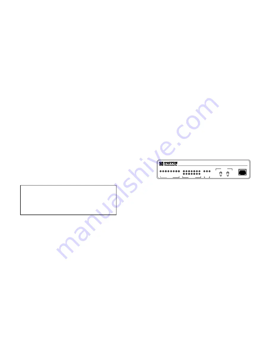
The Model 2530 features twenty-four (24) front panel LEDs that
monitor the line rate, power, the DTE signals, the network connection
and test modes. Figure 5 (below) shows the front panel location of
each LED. Following Figure 5 is a description of each LEDs function.
Power
Glows green when power is present.
Line Rate
The corresponding LED will glow red to indicate the
selected line rate.
TD & RD
Glows red to indicate an idle condition of Binary
“1” data on the respective terminal interface signals.
Green indicates Binary “0” data.
RTS
Glows green to indicate that the Request to Send
signal from the DTE is active.
CTS
Glows green to indicate that the Clear to Send
signal from the modem is active.
DSR
Glows green to indicate that the 2530 has asserted
the Data Set Ready signal.
DCD
Glows red if no carrier signal is being received from
the remote modem. Green indicates that the remote
modem’s carrier is being received.
24
WARNING!
There are no user-serviceable parts in the
power supply section of the Model 2530. Voltage setting
changes and fuse replacement should only be performed by
qualified service personnel. Contact Patton Electronics
Technical support at (301) 975-1007, via our website at
http://www.patton.com, or by e-mail at [email protected],
for more information.
Model 2530
DigiLink-V Dedicated CSU/DSU
Test Mode
Error
No Signal
DTR
DSR
DCD
CTS
RTS
RD
TD
2.4 kbps
4.8 kbps
9.6 kbps
19.2 kbps
38.4 kbps
56 kbps
64 kbps
Power
Test Modes
Loop Pattern
Line
Status
Line Rate
DTE Status
Control Port
Local -
Normal -
Remote -
- Errored
- Off
- Normal
Figure 5. Model 2530 Front Panel Installation of Model


