background image

FAILURE TO OPEN 

1. Check supply gage to be sure it shows 2 psi higher than the

required signal pressure.

2. Turn adjusting knob to top of temperature range. Pressure

should go to within 2 or 3 pounds of supply pressure. If not,
check for dirt in sensitivity screw and ball seating surface.

FAILURE TO CLOSE OR OVERRIDING
DELIVERY PRESSURE

1. Adjusting knob may have been tampered with.

2. If air pressure will not bleed down when adjusting knob is

turned to bottom of range, it is likely that vent is plugged.
Sensitivity screw (7) improperly adjusted (open too wide).

ERRATIC CONTROL

1. Hunting

2. Gradual wandering over too wide a spread.

3. Fast over and under rides are the result of fast load changes,

usually accentuated by the thermostat being located at a point
where it cannot immediately sense a change in conditions.

INSTALLATION FAULTS

1. Poor circulation through heater. Constant circulation should be

employed.

2. Traps on the return may be discharging erratically or may be

improperly installed.

3. Sticky check valve.

4. High lift to condensate hot well. Gravity drainage from heater

should be arranged or return pump installed.
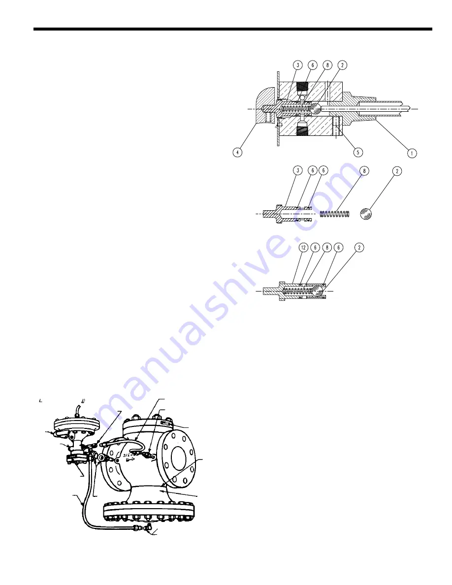
DISMANTLING

1. Remove sensitivity screw (7) and clean.

2. Unlock knob set screw. Loosen and move adjusting knob (4)

out to clear stop on dial plate and lock to shaft. Unscrew
spool (3) from body by rotating adjusting knob
counterclockwise.

3. Care should be taken not to damage O-rings (6). Examine for

nicks and other defects.

4. Examine spool (3) and ball (2) for defects.

5. Clean spool and ball with air pressure.

6. Reassemble.

TESTING & CALIBRATING 

Reverse or Direct Acting
1.

Plug the pilot control air port and apply supply pressure 2 psi
above the control range to the supply air port.

2.

Open the sensitivity screw (7) one turn while establishing a
steady system temperature.

Reverse Acting (T61 & T63) Pilots Only
(Control pressure decreases with increasing temperature)
1.

Turn the spool (3) clockwise to the point where the invar rod,
ball and seat are in contact.  The control gauge should show
pressure near the top of the control range.

2.

Turn the spool counter-clockwise until the control pressure is
at the middle of the range.

3.

Continue to turn the spool counter-clockwise until the low
end of the range is reached. Adjust the sensitivity screw as
required so this occurs within a 5° change on the dial. The
control pressure should vary from the minimum to the
maximum (15 or 30 psi) with a 10° change of the dial setting.
When used with an A-pilot the minimum is 3 psi, when used
with a control valve the minimum is the lower end of the
bench range.

FIGURE 3

FIGURE 2

3

Bleedport Bend

No. 5A  Restriction 

Elbow—Type E

No. 5B  Open 

Elbow—Type E2

No. 4A Bleedport 

Serial No. Plate

Do not
insulate
below
this line

Main Valve
Type E or E2

Control

Pipe

Pilot

Type A85

No. 8B Tee

Serial

No. Plate

Restriction

Bend

1/4" Union

TROUBLE SHOOTING

TYPE T61, T63  

TYPE T62

Summary of Contents for P-K Compact

Page 1: ......

Page 2: ......

Page 3: ......

Page 4: ......

Page 5: ......

Page 6: ......

Page 7: ......

Page 8: ...ontinue to follow the installation instructions supplied in this manual for the T61 temperature controller and J or K series pneumatic control valve The T61 temperature controller should be set at des...

Page 9: ...Hot Water Dump Solenoid Spence T61 Temp Controller Steam Valve Shut Off Solenoid Spence J or K Series Pneumatic Control Valve Vacuum Breaker DRAWING 1...

Page 10: ......

Page 11: ...8 113 4 91 4 111 4 331 2 47 50 226 79 74 251 298 235 286 15 2 21 21 2 93 8 51 4 45 8 117 8 111 4 72 65 238 133 118 302 286 33 3 10 61 8 53 8 117 8 111 4 84 80 254 155 136 302 286 39 4 117 8 71 8 73 8...

Page 12: ...accordance with instructions furnished by the manufacturer of these items Connect necessary air lines and or electrical connections to diaphragm chamber and valve mounted accessories Use 1 4 O D tubi...

Page 13: ...si Do not exceed 20 psi Reverse Acting Fail Closed Air to Open FC ATO Direct Acting Fail Open Air to Close FO ATC Based on 20 psi air supply with positioner Based on 30 psi air supply K1 K4 ACTUATOR S...

Page 14: ...r direct or reverse action Be sure piston spring recesses line up between casing ribs as shown in Figure 8C Lubricate bushing O ring 8 and insert actuator stem through bushing Re attach upper casing 2...

Page 15: ...stem 34 into actuator stem 16 until plug stem assembly stops at upper limit of travel and or a slight downward movement of actuator stem is detected Turn stem nuts up body stem and tighten them to loc...

Page 16: ...114 05 29 TAILPIECE GALV IRON SX227 SMP462 SMP463 SBB227 SMP465 SMP593 30 BODY BRONZE 292B110 01 292B110 01 SAM1167B SAN1167B SAN1167B 564B116 01 31 CAP BRASS 557B101 01 SB312E SB312E SB312E 32 TRAVEL...

Page 17: ...teel 5 02860 0 5 02856 0 5 02860 0 35 Blind flange Cast iron 4 17334 0 4 17337 0 4 17334 0 36 Gasket Graphite 5 02367 1 5 02369 1 5 02371 1 37 Disc stem 304 ss 4 17333 0 4 17340 0 4 17344 0 38 Nut C10...

Page 18: ...CI powder coat 1 10 Stem nut Steel 5 13374 0 1 11 Stem washer 316 ss 5 12963 0 1 3 12 Seal washer Steel 5 13203 0 1 13 Piston 316 ss 1 14 Casing bolt long 304 ss 5 04889 0 2 15 Diaphragm 36 sq in Nit...

Page 19: ...steam pressure It is normally closed being held so by initial pressure on the disc and by an internal main spring The pressure pilot is actuated by means of an air signal applied to it s diaphragm Th...

Page 20: ...t At this point factors such as thermostat location trapping and valve size should be reexamined If the regulator swings immediately on startup and does not settle out and decreasing the sensitivity b...

Page 21: ...sting knob counterclockwise 3 Care should be taken not to damage O rings 6 Examine for nicks and other defects 4 Examine spool 3 and ball 2 for defects 5 Clean spool and ball with air pressure 6 Reass...

Page 22: ...T61 T63 T64 Reverse Acting 08 11507 01 These parts furnished in Repair Kit When ordering parts it is essential that the pilot type service and serial number be stated Select part by item number but or...

Page 23: ...rap below and close to the equipment being drained avoiding long lengths of horizontal piping leading to the steam trap 2 Pitch all horizontal inlet lines toward the steam trap to help eliminate poten...

Page 24: ......

Page 25: ......

Page 26: ......

Page 27: ......

Page 28: ......

Page 29: ......

Page 30: ......

Page 31: ...lve bonnet slightly and rotate to desired position Do not rotate the diaphragm assembly with the valve bonnet 5 Replace bonnet screws and torque in a crisscross manner to 95 10 in lbs 10 7 1 1 Nm 6 Po...

Page 32: ...ment If parts are worn or damaged install a complete ASCO Rebuild Kit Valve Reassembly 1 Lubricate body gasket and solenoid base gasket with DOW CORNINGr 200 Fluid lubricant or an equivalent high grad...

Page 33: ...icates Parts Supplied In ASCO Rebuild Kits solenoid base sub assembly solenoid base sub assembly core spring core assembly core spring core assembly diaphragm spring small end of spring to seat in cup...

Page 34: ...y gasket solenoid base core spring stem stem spring stem bonnet mounting bracket two positions optional bleed hole core spring wide end in core first closed end protrudes from top of core stem pin Ind...

Reviews: