


SERIE 5000
6
CONNECTIONS
3
CONNESSIONI
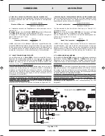
3.5 PRECEDENZA E SEGNALE DI PREAVVISO
Chiudendo i contatti della morsettiera
PRIORITY
[
13
] viene
ammutolito il segnale presente all presa
INPUT
[
15
]; la chiusura del
contatto genera un segnale di preavviso a due toni (CHIME) se il selettore
CHIME
[
12
] si trova in posizione
ON
.
É possibile modificare il livello del segnale di preavviso agendo sul trimmer
semifisso
VR301
posto sul circuito Priority (vedi par. 2.3).
3.6 USCITE DI POTENZA
Le uscite di potenza per i diffusori sono disponibili sulla morsettiera [
18
].
È possibile realizzare un impianto di diffusione sonora utilizzando sia
diffusori a bassa impedenza, sia diffusori dotati di traslatore di linea.
In entrambi i casi il carico complessivo non deve essere tale da
sovraccaricare lamplificatore: non applicare cioè diffusori o gruppi di
diffusori con impedenza più bassa di quella nominale della presa alla
quale sono collegati. Si raccomanda inoltre di porre particolare attenzione
al calcolo delle impedenze nel caso si debbano realizzare impianti di
diffusione misti (a bassa impedenza e a tensione costante).
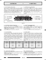
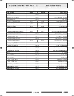
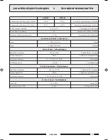
In tabella 3.6.1 sono riportati i valori nominali di tensione ed impedenza
per le diverse uscite.
Uscita
8
Ω
50 V
70 V
100 V
Tabella 3.6.1
AW5240
43,8 V
10,4
Ω
20,4
Ω
41,7
Ω
AW5120
31 V
20,8
Ω
40,8
Ω
83,3
Ω
3.6 POWER OUTPUTS
The power outputs for the loudspeakers are available on the terminal
strip [
18
]. It is possible to set up a sound-broadcasting system
using either low-impedance loudspeakers or loudspeakers equipped with
a line transformer. In both cases the overall load must not be such as to
overload the amplifier. This means that you must not apply loudspeakers
or groups of loudspeakers with an impedance lower than the rated
impedance of the socket to which they are connected. It is also
necessary to pay particular attention to calculating the impedance values
if mixed broadcasting systems (low impedance and constant voltage)
are to be set up.
Table 3.6.1 shows voltage and impedance rated values for the various
outputs.
Output
8
Ω
50 V
70 V
100 V
Table 3.6.1
AW5240
43,8 V
10,4
Ω
20,4
Ω
41,7
Ω
AW5120
31 V
20,8
Ω
40,8
Ω
83,3
Ω
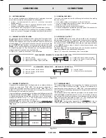
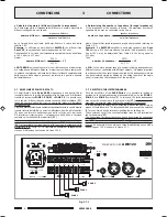
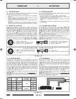
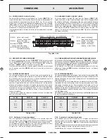
3.4 USCITA MUSIC ON HOLD (MOH)
A questi morsetti [
9
] e' disponibile il segnale presente allingresso
INPUT
[
15
]; tale segnale non e' soggetto allazione di precedenza microfonica o
telefonica. In particolare, l'uscita bilanciata a trasformatore (morsetti
1
-
2
-
3
di fig. 3.4.1) puo' essere utilizzata per il pilotaggio di un ulteriore
amplificatore, di un centralino telefonico od altro; l'uscita di potenza
(morsetti
3
-
4
di fig. 3.4.1) e' in grado di pilotare direttamente un piccolo
altoparlante monitor da 8
Ω
con potenza massima di 1 W.
É possibile regolare il livello di uscita agendo sul controllo
LEV.
[
8
].
Fig. 3.4.1
3.4 MUSIC ON HOLD OUTPUT (MOH)
The signal available on
INPUT
[
15
] is also available on these terminals
[
9
]. This signal is not affected by the use of telephone precedence.
In particular, the balanced transformer output (strips
1
-
2
-
3
, Fig. 3.4.1)
can be used to drive an additional amplifier, a telephone exchange or
other equipment. The power output (terminals
3
-
4
in Figure 3.4.1) is
capable of driving directly a small 8
Ω
monitoring loudspeaker with a
maximum output of 1 W.
It is possible to adjust the output level by means of the
LEV.
control [
8
].
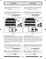
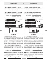
3.6.1 Sistemi a bassa impedenza
In applicazioni che richiedono luso di pochi altoparlanti, la linea di
collegamento può essere connessa tra il terminale comune
0
e la presa
8
Ω
Ω
Ω
Ω
Ω
della morsettiera [
18
].
Il collegamento degli altoparlanti, di tipo serie o parallelo o misto, deve
fornire unimpedenza calcolata pari o superiore ad 8
Ω
.
In figura 3.6.1 é riportato un esempio di collegamento.
3.6.1 Low-impedance systems
In applications that require the use only of a few loudspeakers, the
connecting line may be connected between the common terminal
0
and
the
8
Ω
Ω
Ω
Ω
Ω
socket of the terminal strip [
18
].
The loudspeaker connection, whether of the serial or parallel type or
mixed, should provide an impedance calculated to be equal to or higher
than 8
Ω
. An example of a connection is shown in Figure 3.6.1.
3.5 PRIORITY AND WARNING SIGNAL
If the contacts of the
PRIORITY
terminal strip [
13
] are closed, the
signal on the
INPUT
socket [
15
] is muted. Closing the contact causes a
two-tone warning signal (CHIME) to be generated. The
CHIME
switch
[
12
] is in the
ON
position.
It is possible to change the level of the warning signal by means of the
semi-fixed trimmer
VR301
on the Priority circuit (see point 2.3).
5
: TEL (massa schermo)
(
GND
and shield)
6
: TEL (ingresso - lato freddo)
(input - cold side)
7
: TEL (ingresso - lato caldo)
(input - warm side)
1
: 600
Ω
(linea - lato caldo)
(line - warm side)
2
: 600
Ω
(linea - lato freddo)
(line - cold side)
3
: massa e schermo
GND
and shield
4
: 1W/8
Ω
uscita altoparlanti
loudspeakers output
11-542.p65
26/10/01, 14.20
6


