2.5 INSTALLATION OF THE CHIMNEY
The flue is of great importance for the regular functioning of a forced draft solid fuel
heating appliance, its installation is a very important operation for the functioning of the
stove, it is therefore essential that the flue is built at state of the art and always kept in
perfect efficiency.
Check with the local authorities if there are any restrictive regulations regarding the
combustion
air
intake,
the
smoke
exhaust
system,
the
flue.
The components that make up the smoke evacuation system must be declared
suitable for the specific operating conditions and provided with CE marking, the pipe
must be smoke-tight, have a vertical course without bottlenecks, be made of materials
impermeable to fumes, condensation, thermally insulated and suitable to withstand
normal
mechanical
stress
over
time.
It must be spaced from combustible or easily flammable materials with an air gap or
insulating
materials.
The use of flexible or extensible metal pipes or unsuitable material is not allowed.
Single or double-walled steel pipes with a nominal internal diameter of 80 mm or 100
mm can be used depending on the model.
The minimum draft must be 12 Pa, the optimal one 15 Pa.
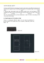
The flue must be brought to the roof and at the base of it must be mounted a "T" fitting
for smoke inspection with cap (figure 4). if it is not possible to make a totally vertical
barrel (recommended operation), it is advisable to make a maximum of 3 changes of
direction, in addition to that deriving from the rear connection of the stove, using the "T"
fittings with inspection cap. any variation of the discharge path.
The horizontal flue sections, if necessary, must have a maximum length of 2-3 m and a
slope of 5-10 °, in order to avoid the deposit of ash. For horizontal> 2 m, an increase in
the section of the flue is strongly recommended (e.g. from 80mm to 100mm). (figure 5).
fig. 4
fig. 5
9
Summary of Contents for SOFIA
Page 1: ...Produzione stufe e termostufe a pellets e policombustibili User manual SOFIA Ermetic Stove ...
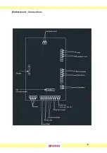
Page 21: ...Motherboard Connections 18 ...
Page 27: ...CONSOLE 24 5 DISPLAY 5 1 ...
Page 28: ...28 25 ...
Page 29: ...USER MENU 26 5 2 USER MENU ...
Page 30: ...USER MENU 09 Technical menu 10 Abilita combustibile 11 Tipo combustibile under key 1 2 27 ...
Page 31: ...USER MENU 28 ...
Page 32: ...USER MENU 29 ...
Page 33: ... and so on up to PROGRAM 4 USER MENU 30 ...
Page 34: ...USER MENU 31 ...
Page 50: ...47 ...


