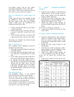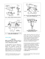
Step 11—Install Pipe Splice and Guide Plate
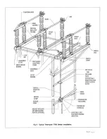
When the structure height exceeds 23 feet, a
pipe splice and a guide plate are furnished
and should be installed as shown in Fig. 6.
The pipe spice and both pieces of pipe are
predrilled to receive the 5/8” diameter pins.
The guide plate should not be solidly
mounted until after the vertical pipe has
been completely installed. Then bolts
holding the guide plate on the structure
should be tightened in order that the holes in
the guide plate line up with the normal
position of pipe. This assures that there is no
binding.
Step 12—Install Operating Mechanism
Either a swing handle or a worm gear
mechanism is (normally) supplied for
manual switch operation.
Swing Handle Operator
To install the swing handle operator:
With ground strap in place on vertical operating
pipe, slide handle and handle lock plate over the
end of the vertical operating pipe. Fasten the
lock plate at the proper location. Recommended
height for the lock plate is 3 ft. 6 in. above
ground.
Note:
The lower end of the vertical operating
pipe should extend through the lock plate at
least 3 inches. It may extend as much as 3 feet
or more, just so it doesn’t touch the ground or
column footing.
The lock plate assembly consists of two
castings, mounted on the pipe guide plate, which
can be easily adjusted in an arc to provide the
required rotation. These act as locks for the
manual operating handle when it is dropped
from the operating position. The handle must be
raised to a horizontal position for operation.
With the switch in the fully closed position, set
the handle clamp so its set screws are 4 inches
above the lock plate and its vertical centerline is
at or near as possible to the closed position.
Temporarily fasten the handle to the pipe with
the set screws. Operate the switch and move the
adjustable lock castings until they exert pressure
against the handle in both the open and closed
positions of the switch. This provides a slight
torsional wind-up in the operating pipe. Tighten
the two piercing set screws on the handle clamp
until holes are punched into the pipe and
continue until the screws are firmly seated.
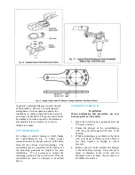
Worm Gear Mechanism
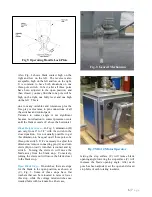
With ground strap in place on vertical operating
pipe, slide worm gear mechanism (Fig. 8) over
the vertical operating pipe and attach it to the
structure. Remove the small position indicators,
which are attached to the worm gear coupling
with Allen set screws. Tighten hex head set
screws in the coupling until the vertical
operating pipe is pierced. The three-pole switch
should now be operated manually to check for
proper adjustment. If all stops at switch
elevation have been set, including the offset
bearing, then it is safe to reinstall the position
indicators on the worm gear mechanism. These
indicators should not quite touch the raised boss
on the worm gear housing in either the open or
closed position. There is a possibility of damage
to the indicators or the coupling if this is not
observed
Motor Operator
For remote operation, a motor operator is
supplied and it should be installed per the
instructions supplied with it.
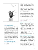
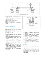
Step 13—Arcing Horn Installation (When
Supplied)
When arcing horns are used on switches, they
should be installed and adjusted after mounting
the switches on the structure. Arcing horns are
furnished only when horn gap switches are
ordered. Fig. 10 shows arcing horns used on
switches 8.25 thru 169 kV. The movable strait
horn (C) is assembled be screwing it into the
blade end. Tighten the locking nut seat securely
against the end of the blade (A). The stationary
horn is positioned properly on the jaw with the
saddle clamp, and bolted (B). This stationary
horn should be adjusted or even bent slightly to
give light contact pressure between the two
horns over the entire length if the movable horn.
Arcing horns for 242 kV switches are essentially
the same as Fig 10 with the stationary horn
contacting the movable horn at the surface
between the end of the blade and small corona
ball which is affixed at the end of the movable
horn.
Arcing horns for switches 362 thru 8000kV do
not use a movable horn. Instead the stationary
Summary of Contents for TTR6
Page 1: ...IB TTR6 B May 2012 ...
Page 6: ...5 P a g e ...

