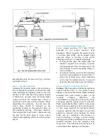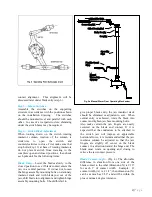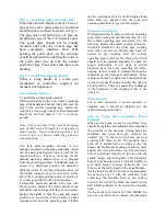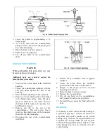
and adjusting nuts are shown in Fig. 1 and are
explained in step 3.
Step 2—Assemble Insulators
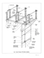
Assemble the insulator stacks to the switch base.
Do not disturb the position of the switch crank
when mounting the insulator stack to the rotor
bearing, as the crank has been properly located
at the factory. In some cases, involving higher
voltage switches, the installer may choose to
mount the switch bases on the structure before
assembling the insulators. In such cases the
switch bases should be mounted on the
supporting structure in the positions shown on
the installation drawing. The bases should be
level and parallel to each other. Make sure that
the base for the drive phase is in the correct
location and operating cranks are at their proper
angles.
Step 3—Insulator Stack Alignment
Lower voltage switches 8.25 thru 72.5kV
generally do not require insulator stack
alignment. Where required, the insulator stacks
of switches thru 242kV can be aligned using
open-end shims or leveling screws and/or
adjusting nuts (Fig. 1) if supplied (optional).
•
If using shims, place the shims under the
insulator supports (rotor bearing or spacer
mounting flange) where the bolts secure the
rotor bearing or spacer mounting flange to
the switch bases.
•
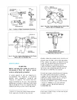
If optional leveling screws and/or adjusting
nuts have been supplied, as shown in Fig. 1,
adjust the leveling screw and/or adjusting
nut to align the insulator stacks. Loosen all
hardware before jacking to prevent binding.
Step 4—Mount Current Carrying Parts
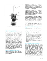
Caution:
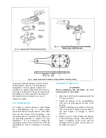
When uncrating switches having blade
counter balances (Fig. 3), be careful to keep
linkage on dead center until the blade and hinge
assembly have been bolted in place on the
insulator columns. Otherwise, the
counterbalance springs may collapse the hinge
end toggle, possible causing injury to workmen.
Make certain that the base crank is in the proper
position when mounting current carrying parts,
i.e. base crank rotated to the maximum counter
clockwise position with the blade closed. Care
should be exercised when hoisting the blade
hinge and jaw assemblies into position to
prevent scratches or damage to these current-
carrying parts. When assembling the jaws on the
insulator columns, leave the mounting bolts
finger tight. This will permit the jaw base to be
rotated and shifted slightly for subsequent
3 |
P a g e
Summary of Contents for TTR6
Page 1: ...IB TTR6 B May 2012 ...
Page 6: ...5 P a g e ...

