Step 7—Mount Offset Bearing
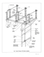
For those installations requiring an offset
bearing, mount the offset bearing and its
supporting base on the structure in the position
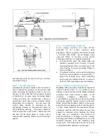
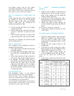
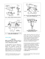
shown on the installation drawing. Fig. 6 shows
a typical arrangement using the offset bearing.
Check operating crank for proper length radius
and angle, and stop crank for correct position. If
the offset bearing has an adjustable crank, it is
sometime necessary to add ¼” to ½” to the trial
radius given on the control drawing to get
required travel to switch blades. This additional
length allows for lost motion and clearances in
pin holes and will also provide a definite audible
sound accompanied by a reasonable amount of
deflection in the structural members when the
crank crosses the dead canter position. This
serves as a signal to the operator that the switch
is either fully open or closed.
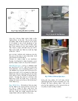
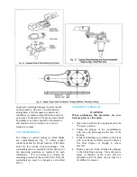
Step 8—Adjust the Multi-Angle Crank
The crank is identified in Fig. 5. This crank is
supplied on the operating pole unit connected to
the offset bearing.
3” Bolt Circle Insulators have a multi-angle
crank that permits 333 degrees of angular
adjustment with a crank location every 9
degrees, which results in adjustments to within
4-1/2 degrees of desired position.
5” Bolt Circle Insulators have a multi-angle
crank that permits 336 degrees of angular
adjustment with a crank location every 12
degrees which results in adjustments to within 6
degrees of the desired position.
In some adjustments, the multi-angle crank may
be in such a position as to interfere with the stop
projection on the switch crank. If this is the
case, then remove this projection. The other two
poles will regulate the blade travel on this unit.
Note: The multi-angle crank should be set so
that it forms an angle of approximately 45
degrees with the offset link in either switch
position, open or closed.
Step 9—Install Interphase and Offset Crank
Rods
With all blades in the closed position, install the
interphase rods and offset crank rod as follows:
a.
Lengthen the interphase rods that are in
compression during opening, as much as
possible, yet allowing for the pins to be
inserted.
b.
On the rods that are in tension during
opening, shorten them as much as possible,
yet allowing for the pins to be inserted.
c.
The offset crank rod between the outboard
bearing and the driven switch should be
handled the same way
d.
For lubrication of pins and bearing areas, see
Table 2
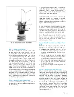
Step 10—Install Vertical Operating Pipe
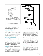
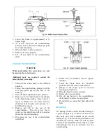
Attach vertical operating pipe to rotor bearing
shaft, or to offset rotor bearing shaft with supplied
coupling pins, see Fig. 5A. At this point, check
drawings for accessory equipment (auxiliary
switches, mechanical interlocks, position
indicators, ground straps, etc.) which mounts on
vertical operating pipe and install before continuing
installation. The vertical pipe is predrilled at one
end for a 5/8” diameter pin, two of which are
shipped, together with a coupling, in a bag, for
connection to the offset bearing shaft (or on the
pole unit rotor bearing in the case of direct
connection switches)
7 |
P a g e
Summary of Contents for TTR6
Page 1: ...IB TTR6 B May 2012 ...
Page 6: ...5 P a g e ...

