background image

!

DC Power Supply

Basic Operation

20

Safety Feature: Whenever the Power Supply enters Constant DC mode, the output voltage is 
automatically set to zero.

Set Voltage

Rotate Coarse knob to change the output voltage by 1.0 V per detent; 

rotate the Fine knob slowly to change the voltage by 0.01 V per detent, or quickly to 
change the voltage by 0.04 V per detent. 

By default the output voltage is limited to 18 V, but this limit may be set lower. If a 
load is connected to the Power Supply, the highest allowable voltage may also be lim-
ited by the maximum-current setting, which is 1 A by default. See “Maximum Val-
ues” 
below for instructions on setting these maximums.

Voltage and Current Display

To switch the display from voltage to current, 

press 

 (DISPLAY); the output current appears on the display, and the Current LED 

lights. Press 

 (DISPLAY) again to switch the display back to voltage.

When current is displayed, rotating the Coarse and Fine knobs adjusts the 

voltage

Note that the current is 

not

 regulated. If the load changes the voltage will remain con-

stant at its set value, but the current will change.

In Constant DC mode you can set the display to cycle between voltage and current. 
Press 

and


hold


 (SET) while rotating the Coarse knob to set the cycle time in sec-

onds (while you are making this adjustment, the Time LED is lit and the display 
shows the cycle time); then release the button. The display alternates between current 
and voltage at a rate determined by the cycle time that you set. Press 

 (DISPLAY) 

to pause the display on voltage or current; press 

 again to restart alternating. To 

disable alternating display mode, press 

and hold


 (SET) while rotating the knobs to 

set the cycle time to zero.

You can also press and hold 

 (STOP) to reset both the cycle time and the voltage to zero.

Output Switch-off

To temporarily switch off the output, press 

. The Voltage 

LED blinks quickly to indicate that the actual output voltage is zero even though the 
voltage 

setting

 (which may not be zero) is displayed. While the output is switched off, 

you can turn the Coarse and Fine knobs to adjust the voltage setting. Press 

 again 

to switch the output voltage back on.
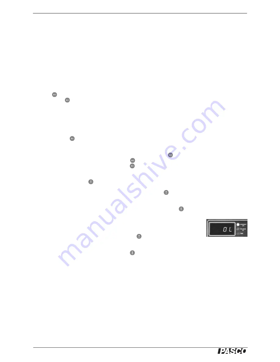
Over-current 

If output current exceeds the maximum-current setting (see “Maxi-

mum Values” below), the output voltage drops to zero, the display reads 

OL

 (for 

“overload”), and Current LED flashes amber. Press 

 (START) to resume normal 

operation.

Reset Output and Display

Press 

and hold


 (STOP) to set the voltage to zero 

and set the display to show voltage. The output and display are also reset in this way 
if you turn the Function knob and return it to Constant DC mode.

Maximum Values

By default, the Power Supply is set for a voltage limit of 18 V and a maximum current 
of 1 A. The Power Supply will not allow its output to exceed the voltage limit, and it 
will turn off the output if it exceeds the maximum current. To lower the 
maximum-allowable voltage or current, turn the Function knob to SET MAX. In this 
mode you can also set the Power Supply to turn off the output after a specified time.

In SET MAX mode, the display shows maximum-value 

settings; 

the actual output 

voltage is always zero.

To prevent accidental damage to lab equipment, set an appropriate maximum voltage or current 
for the equipment that the Power Supply will be used with.

Display reads OL if the 

maximum current is 

exceeded

Summary of Contents for PI-9877

Page 1: ... DC Power Supply PI 9877 Instruction Manual 012 09125A ...

Page 2: ... Power Supply Table of Contents Contents Introduction 3 Typical Uses 4 Specifications 4 Tutorial 7 Basic Operation 19 Standard Functions Rectangle Ramp and Stair 22 Custom Program 28 Technical Support 35 ...

Page 3: ...ources 0 18 volts at up to 1 amp You can use the Power Supply as a simple constant voltage source or take advantage of its advanced features to output periodic functions and custom pro grams Included Equipment Part Number DC Power Supply PI 9877 AC Power Adapter 540 062 ...

Page 4: ...al Acceleration Tank ME 8957 TD 8513 Heat Conduction Apparatus Power the apparatus with a positive offset rectangle wave see page 22 or sine wave the Power Supply s default custom program see page 28 General Specifications Output Voltage Adjustment 0 18 V Voltage Adjust Resolution 10 mV Voltage Adjust Accuracy 0 25 of setting or 20 mV whichever is larger Current limit Shutdown Programmable 0 010 1...

Page 5: ...ending or descending Alternating stair direction option Programmable number of cycles 1 to 999 or infinite Monitor voltage or current Function 5 SET MAX see page 20 Programmable voltage limit 0 01 18 00 V Programmable maximum current 0 010 1 050 A Automatic shutdown timer 0 01 99 99 hours Hidden Global Maximum voltage 0 01 18 00 V remembered after power off Function 6 PROGRAM Custom program entry ...

Page 6: ...s This device is a programmable power source not a function generator The max imum frequency of the rectangle and ramp functions is 10 Hz The maximum fre quency of the default sine wave custom program is about 0 1 Hz The Power Supply is designed for current flow in one direction out of the posi tive terminal and into the negative terminal In the example illustrated below the Power Supply is switch...

Page 7: ...k at the current draw You can use any resistor from about 20 Ω to 100 Ω but check the power rating to make sure it will not overheat during the tutorial you will apply voltages up to 10 volts Set up POWER and OUTPUT connections 1 Plug the AC adapter into a wall outlet and into the port labeled POWER on the Power Supply 2 Use a pair of banana plug patch cords to connect a load resistor or other dev...

Page 8: ... voltage changes by 0 01 V per detent If you rotate the knob more quickly it changes by 0 04 V per detent Adjust the voltage back to 4 00 V Temporarily switch off output 3 Quickly press and release to temporarily switch off the output The Voltage LED blinks rapidly and the actual output voltage drops to zero though the display still shows the voltage setting Turn the Coarse knob Note that you can ...

Page 9: ... every 2 sec onds Press to pause the display toggling press again to resume Reset output and display 6 Press and hold until the display shows 0 00 Release the button You have just reset the output voltage to zero and the display to voltage For more information about constant DC output see page 19 Function 5 SET MAX Set maximum voltage 1 Turn the Function knob to SET MAX The display briefly shows F...

Page 10: ...hat the countdown has not started yet Display shows auto off Press to start the countdown The Time LED is now lit steadily Turn the Function knob back to Constant DC and set the voltage to 1 V Wait for the remainder of the 36 seconds When the countdown time has elapsed the display shows OFF to indicate that the output has been switched off Press to return the Power Supply to normal operation Setti...

Page 11: ... label printed above the button which indicates what happens when you press the button 4 Try turning the Coarse and Fine knobs the knobs have no effect when the function is running 5 Press and hold for about 1 second to stop running the function Note the STOP label printed below the but ton which indicates what happens when you press and hold the button Minimum voltage set to 2 V 6 Press and hold ...

Page 12: ...a duty cycle of 50 while holding the but ton turn the Coarse knob to change the duty cycle to 10 Press START The output voltage now spends 10 of the time at the maximum voltage and 90 of the time at the minimum voltage Press and hold STOP For more information about the Rectangle Wave func tion see page 22 Function 3 Ramp Ramp with 2 V minimum and 8 V maximum 1 Turn the function knob to Ramp The di...

Page 13: ... starts blinking fast and the display shows 0 the auto repeat setting while holding the button turn the Fine knob to change the auto repeat setting to 2 Press START to run the function The output now completes two ramps and stops automatically A negative auto repeat setting causes a triangle wave 8 Press DISPLAY so that the Time LED is lit Press and hold SET and adjust the auto repeat setting to 2...

Page 14: ...1 00 s 5 Press START to run the function and observe the waveform Note that the top of the stair is determined by the Power Supply s voltage limit setting Press and hold STOP Stair with a negative auto repeat setting 6 Press DISPLAY so that the Time LED is lit again Press and hold SET the Time LED starts blinking and the display shows the auto repeat setting while holding the button adjust the aut...

Page 15: ... sensor be sure to stop the program before it exceeds 10 V Scale Factor of 50 3 Turn the Coarse knob to change the Scale Factor to 50 Press START to play the program again each voltage point is now half of what it was before Press and hold STOP Graph type set to 0 4 Press and hold SET the display shows 1 the graph type setting while holding the button turn the Coarse knob to change the graph type ...

Page 16: ...ero Press START to play the program again The program now alternates between playing forward and backward resulting in a positive offset sine wave Press and hold STOP Program stops before exceeding the voltage limit 7 Turn the Function knob to SET MAX and set the voltage limit to 5 V Turn the Function knob back to PLAY Press START to play the program The output will not exceed the voltage limit ju...

Page 17: ...ess to store that value 4 Press and hold STOP to exit edit mode The display shows P 51 to indicate the num ber of stored points Erase the stored program 5 Press and hold both buttons simultaneously until the display shows EEEE for Erased release the buttons You have just erased the stored program The display now shows P 0 because there are zero stored points 6 To enter a new program press The dis ...

Page 18: ... DC Power Supply 18 T u t o r i a l ...

Page 19: ... Fine knobs adjust the output voltage or the setting shown on the digital display Rotate the Coarse knob to adjust the quantity in large steps rotate the Fine knob to adjust it in small steps The Fine knob is speed sensitive rotating it quickly causes a larger change per detent than rotating it slowly The push buttons and are used to select what is shown on the digital display and to control the o...

Page 20: ...estart alternating To disable alternating display mode press and hold SET while rotating the knobs to set the cycle time to zero You can also press and hold STOP to reset both the cycle time and the voltage to zero Output Switch off To temporarily switch off the output press The Voltage LED blinks quickly to indicate that the actual output voltage is zero even though the voltage setting which may ...

Page 21: ... the countdown has started While the countdown is in progress you can turn the Function knob to any position and operate the Power Supply in the normal way To check the remaining time return to SET MAX mode and press DISPLAY twice so that the Time LED is lit To stop the countdown while the remaining time is displayed press and hold STOP When the countdown time has elapsed the output voltage drops ...

Page 22: ...half the time and low half the time Rectangle Wave Set up 1 Turn the Function knob to The dis play shows the Maximum Voltage parameter and the Voltage LED blinks slowly to show that the Power Supply is in set up mode with no output Turn the Coarse and Fine knobs to set the Maximum Voltage 2 To set the Minimum Voltage press and hold SET until the Voltage LED starts blinking fast While holding the b...

Page 23: ...ir resulting waveforms are illustrated below Ramp Set up 1 Turn the Function knob to The display shows the Maximum Voltage parameter and the Voltage LED blinks slowly to indicate that the Power Supply is in set up mode with no output Turn the Coarse and Fine knobs to set the Max imum Voltage 2 To set the Minimum Voltage press and hold SET until the Voltage LED starts blinking fast While holding th...

Page 24: ...ends on its value as summarized below 4 To set the Auto repeat parameter press and hold SET until the Time LED starts blinking fast While holding the button turn the Coarse and Fine knobs to adjust Auto repeat between 999 and 999 To run the Ramp function press START See Standard Functions Run Mode on page 27 for further instructions Period seconds Adjustment increment seconds 999 to 100 1 99 9 to ...

Page 25: ...ter of the Stair function is always equal to the Power Supply s voltage limit setting Turn the Function knob to SET MAX then turn the Coarse and Fine knobs to adjust the voltage limit 2 Turn the Function knob to The display shows the Step Voltage parameter The Voltage LED blinks slowly to show that the Power Supply is in set up mode with no output Turn the Coarse and Fine knobs to set the Step Vol...

Page 26: ... Time LED starts blinking fast While holding the button turn the Coarse and Fine knobs to adjust Auto repeat between 999 and 999 To run the Stair function press START See Standard Functions Run Mode on page 27 for further instructions Special Application Heat Pulse For calorimeters and other apparatus that use heating resistors you may want to drive the resistor with a pulse of a specific voltage ...

Page 27: ...ss The Voltage LED light blinks fast and output voltage goes to zero though the paused voltage which may not be zero is shown on the display To continue running the function press again 3 To stop running the function and return the Power Supply to set up mode press and hold STOP you can do this while the function is either running or paused The output stops automatically after the number of repeti...

Page 28: ...buttons The Power Supply returns to Program Home mode with the display showing P 0 to indicate that zero points are stored Follow the Append instructions below to enter a new program Append Use Program Append mode to add points to the end of the existing program or start a new program if zero points are stored 1 From Program Home mode press START to enter Program Append mode The display briefly sh...

Page 29: ...ther point turn the Coarse or Fine knob to display the index number of the point that you wish to insert in front of and repeat this step 4 When you are finished editing the program press and hold STOP to return to Program Home mode Tips for Designing a Custom Program Before you start entering a program write it on paper or generate it on a com puter in two columns with index numbers in the first ...

Page 30: ...rogram plays in the only one direction or alternating directions Some examples of parameter combinations and their resulting waveforms are illus trated below For a periodic or repeating function the period depends on the number of programed points the Step Time and the sign of Auto Repeat If Auto Repeat is negative you only need to program the first half of the waveform because the program repeats...

Page 31: ...times Step Time 4 To set the Auto repeat parameter press and hold SET until the Time LED starts blinking fast While still holding the button turn the Coarse and Fine knobs to adjust Auto repeat between 999 and 999 Play Custom Program 1 To play the custom program turn the Function knob to PLAY and press START The Voltage LED lights steadily to indicate that the display shows the actual output volta...

Page 32: ...he Voltage LED flashes amber Press and hold to return the Power Supply to set up mode Example Custom Programs The following tables show some examples of programs and settings with the resulting output Time Delay Long Ramp Settings Graph Type Step Time Auto repeat 1 60 s 1 Voltage values 0 0 0 0 5 5 Use a program like this to make the Power Supply wait for a certain interval after you press before ...

Page 33: ...step function requires each step to have the same width This custom program allows each step to have a different width Settings Graph Type Step Time Auto repeat 1 0 5 s 0 Voltage values 5 0 0 0 0 0 0 0 0 0 5 5 5 5 5 5 5 0 0 0 The standard square wave function allows you to change the duty cycle but all the pulses must have the same width With this custom program you can create almost any pattern o...

Page 34: ...ed points follow the function V 0 06 e0 6 t 1 Just 20 points are sufficient for a close approximation of the function Change the Step Time to a negative value for a decreasing exponential Use this program with negative Step Time to simulate a discharging capacitor Settings Graph Type Step Time Auto repeat 0 0 10 s 0 Voltage values 0 3 8 6 32 8 05 9 50 10 75 11 83 12 79 13 64 14 39 15 06 15 65 16 1...

Page 35: ...nstitutions for reproduction of any part of this manual providing the reproductions are used only in their lab oratories and classrooms and are not sold for profit Reproduction under any other circumstances without the written consent of PASCO scientific is prohibited Trademarks PASCO PASCO scientific and DataStudio are trademarks or registered trademarks of PASCO scientific in the United States a...

Page 36: ......

Reviews: