!
DC Power Supply
12
T u t o r i a l
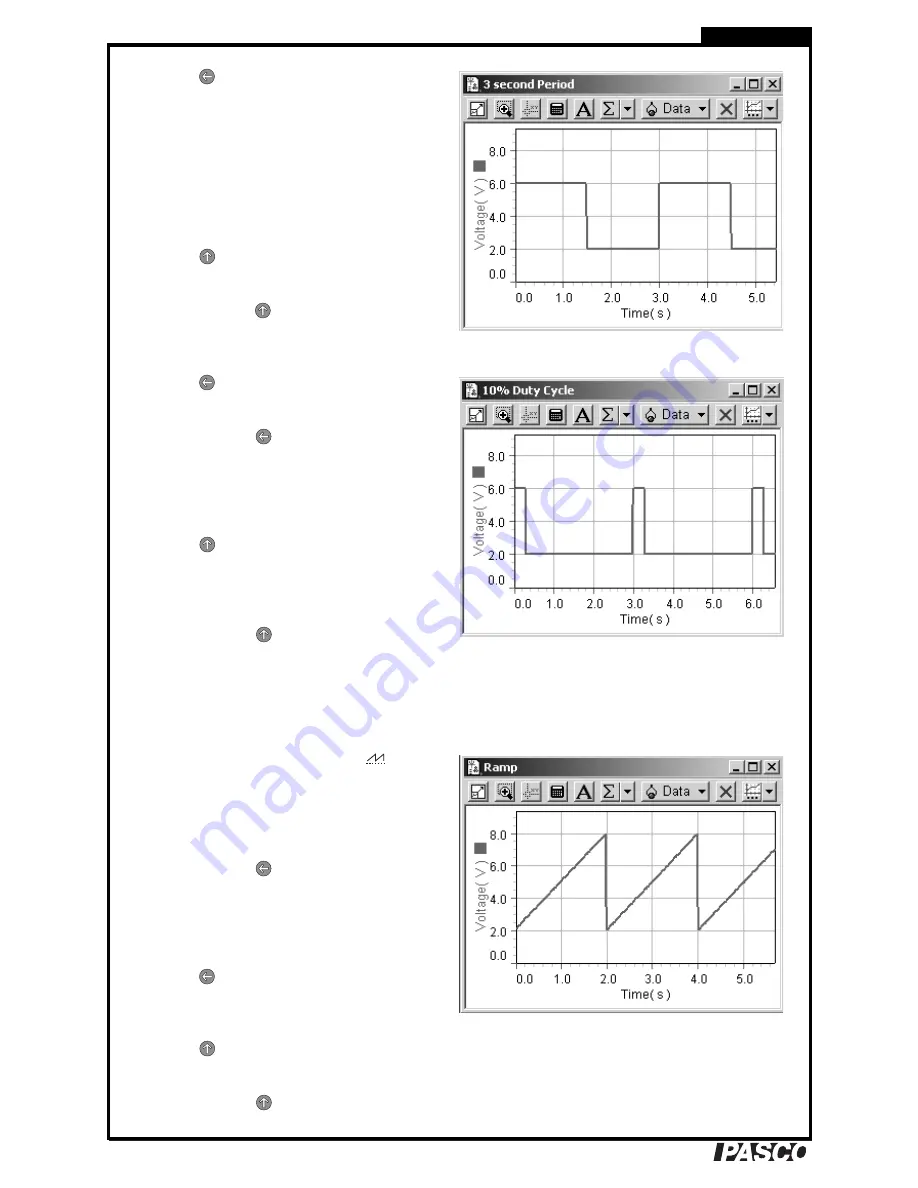
Period set to 3 s
7.
Press
. The Time LED lights and the dis-
play shows the rectangle wave’s period (in
seconds). Turn the Coarse and Fine knobs to
change the period to 0.13 s. (By turning the
Fine knob slowly you can adjust the period
in 0.01 s increments.)
Turn the Coarse and Fine knobs to set the
period to 3.00 s.
Press
(START). The output voltage now
completes a full cycle every 3 seconds.
Press
and hold
(STOP). Note that the dis-
play has gone back to showing the maxi-
mum-voltage setting.
Duty cycle of 10%
8.
Press
(DISPLAY) so that the Time LED
is lit.
Press
and hold
(SET); the Time LED
starts blinking and the display shows
50
(for
a duty cycle of 50%);
while
holding
the but-
ton, turn the Coarse knob to change the duty
cycle to 10%.
Press
(START). The output voltage now
spends 10% of the time at the maximum
voltage and 90% of the time at the minimum
voltage.
Press
and hold
(STOP).
For more information about the Rectangle Wave func-
tion, see page 22.
Function 3: Ramp
Ramp with 2 V minimum and 8 V maximum
1.
Turn the function knob to Ramp (
). The
display briefly shows
F3
, then
18.00
(the
ramp’s maximum-voltage setting).
2.
Set the maximum voltage to 8.00 V.
3.
Press
and hold
(SET); the Voltage LED
starts blinking fast and the display shows the
minimum-voltage setting;
while holding
the
button, adjust the minimum voltage to
2.00 V.
4.
Press
(DISPLAY); the Time LED lights
and the display shows the ramp’s period. Set
the period to 2.00 s.
5.
Press
(START) to run the function and
observe the waveform.
Press
and hold
(STOP).
Summary of Contents for PI-9877
Page 1: ... DC Power Supply PI 9877 Instruction Manual 012 09125A ...
Page 18: ... DC Power Supply 18 T u t o r i a l ...
Page 36: ......


