background image

www.parweld.com

4

1.0 Safety Precautions

ELECTRIC SHOCK can kill.

Touching live electrical parts can cause fatal shocks or severe burns. 
The electrode and work circuit is electrically live whenever the output 
is on. The input power circuit and machine internal circuits are also 
live when power is on. In semi automatic or automatic wire welding, 
the wire, wire reel, drive roll housing, and all metal parts touching the 
welding wire are electrically live. Incorrectly installed or improperly 
grounded equipment is a hazard.

Do not touch live electrical parts.

Wear dry, sound insulating gloves and body protection.

Insulate yourself from work and ground using dry insulating mats 
or covers big enough to prevent any physical contact with the work 
ground.

Additional safety precautions are required when any of the following 
electrically hazardous conditions are present: in damp locations 

or while wearing wet clothing; on metal structures such as floors, 
gratings, or scaffolds; when in cramped positions such as sitting, 

kneeling, or lying; or when there is a high risk of unavoidable 
or accidental contact with the work piece or ground. For these 
conditions, use the following equipment in order presented: 1) a 
semi automatic DC constant voltage (wire) welder, 2) a DC manual 
(stick) welder, And, do not work alone!

Disconnect input power before installing or servicing this equipment. 
Lockout/tagout input power according to Safety Standards.

Properly install and ground this equipment according to national and 
local standards.

Always verify the supply ground - check and ensure that input power 
cable ground wire is properly connected to ground terminal in the 
receptacle outlet.

When making input connections, attach proper grounding conductor 

first - double-check connections.

Frequently inspect input power cable for damage or bare wiring - 
replace cable immediately if damaged - bare wiring can kill.

Turn off all equipment when not in use.

Do not use worn, damaged, under sized, or poorly spliced cables.

Do not drape cables over your body.

If earth grounding of the work piece is required, ground it directly 
with a separate cable.

Do not touch electrode if you are in contact with the work, ground, or 

another electrode from a different machine.

Use only well-maintained equipment. Repair or replace damaged 
parts at once. Maintain unit according to manual.

Wear a safety harness if working above floor level.

Keep all panels and covers securely in place.

Clamp work cable with good metal-to-metal contact to work piece or 
worktable as near the weld as practical.

Insulate work clamp when not connected to work piece to prevent 
contact with any metal object.

Welding produces fumes and gases. Breathing these fumes and 
gases can be hazardous to your health.

FUMES AND GASES can be hazardous.

Do not breathe the fumes.

Ensure local extraction is effective or use personal filtration system. 

Welding fume can be carcinogenic.

Read and understand the Material Safety Data Sheets (MSDS’s) and 
the manufacturer’s instructions for metals, consumable, coatings, 
cleaners, and de-greasers.

Work in a confined space only while wearing an air-supplied 

respirator. Always have a trained watch person nearby. Welding 
fumes and gases can displace air and lower the oxygen level 
causing injury or death. Be sure the breathing air is safe.

Do not weld in locations near de-greasing, cleaning, or spraying 
operations. The heat and rays of the arc can react with vapours to 
form highly toxic and irritating gases.

Do not weld on coated metals, such as galvanized, lead, or cadmium 
plated steel, unless the coating is removed from the weld area, the 
area is well ventilated, and while wearing an air-supplied respirator. 

The coatings and any metals containing these elements can give off 

toxic fumes if welded.

ARC RAYS can burn eyes and skin.

Arc rays from the welding process produce intense, visible and 
invisible (ultraviolet and infrared) rays that can burn eyes and skin. 

Sparks fly off from the weld.

Wear an approved welding helmet fitted with a proper shade of filter 

lenses to protect your face and eyes when welding or watching

Wear approved safety glasses with side shields under your helmet.

Use protective screens or barriers to protect others from flash, glare 

and sparks; warn others not to watch the arc.

Wear protective clothing made from durable, flame resistant material 

(leather, heavy cotton, or wool) and foot protection. Welding on 
closed containers, such as tanks, drums, or pipes, can cause them 

to blow up. Sparks can fly off from the welding arc. The flying sparks, 
hot work piece, and hot equipment can cause fires and burns. 

Accidental contact of electrode to metal objects can cause sparks, 

explosion, overheating, or fire. Check and be sure the area is safe 

before doing any welding.

Summary of Contents for XTM 211Di

Page 1: ...OPERATOR MANUAL ISSUE 1 XTM 211Di ...

Page 2: ...tenance this equipment should provide years of reliable service All our systems conform to ISO9001 2015 and are independently audited by NQA The entire product range carries the CE mark and is constructed in accordance with European directives and the product specific standards where they apply Further Information Parweld is the UK s leading supplier of MIG TIG and Plasma torches and consumables F...

Page 3: ...Control MIG Torch 11 7 5 MIG Welding Procedure 12 7 6 MMA Welding 12 7 7 TIG Welding 12 7 7 1 TIG Torch Selection 12 7 7 2 TIG Torch Installation 13 7 7 3 TIG Welding Setup 13 15 7 7 4 TIG Welding Guide 15 7 7 5 DC TIG Welding No Pulse 15 16 7 7 6 AC TIG Welding No Pulse 16 17 7 7 7 TIG Welding With Pulse 17 18 7 8 Saving to Memory 18 7 9 Process Switch 18 19 8 0 Fault Finding 19 22 8 1 MIG Weldin...

Page 4: ...or replace damaged parts at once Maintain unit according to manual Wear a safety harness if working above floor level Keep all panels and covers securely in place Clamp work cable with good metal to metal contact to work piece or worktable as near the weld as practical Insulate work clamp when not connected to work piece to prevent contact with any metal object Welding produces fumes and gases Bre...

Page 5: ...h bare handed Allow cooling period before working on gun or torch To handle hot parts use proper tools and or wear heavy insulated welding gloves and clothing to prevent burns MAGNETIC FIELDS can affect pacemakers Pacemaker wearers keep away Wearers should consult their doctor before going near arc welding gouging or spot welding operations NOISE can damage hearing Noise from some processes or equ...

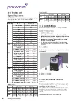
Page 6: ...60 100 140A 125A 100A 200A 150A 120A MMA 35 60 100 25 60 100 110A 90A 70A 200A 140A 120A 4 0 Installation Read entire installation section before starting installation SAFETY PRECAUTIONS ELECTRIC SHOCK can kill Only qualified personnel should perform this installation Only personnel that have read and understood the Operating Manual should install and operate this equipment Machine must be grounde...

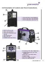
Page 7: ...onnector 15 TIG Torch Gas Connector 4 MIG Torch Connector 5 Work Lead Connector 6 TIG Torch Electrode Holder Socket 7 Wire Spool Holder 8 Wire Feed Unit 9 Multifunction Control Knob 1 Power Switch for Incoming Mains 2 QF Incoming Gas Connection MIG 3 QF Incoming Gas Connection TIG 1 2 9 4 6 8 7 5 11 12 13 10 5 0 Description of Controls and Torch Connections 3 15 14 ...

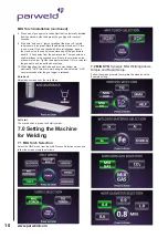
Page 8: ...een Press to select Press and hold to step back in menu tree Short press at end of menu returns to start menu 6 2 Language of Operation Short Press 1 sec to return to start menu 6 3 Process Selection TIG Synergic TIG Welding Setup MMA Synergic MMA Welding Setup MIG MAN Manual MIG Welding Setup MIG SYN Synergic MIG Welding Allows Simple and Rapid Setup ...

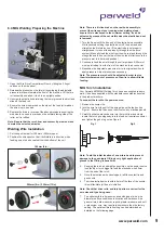
Page 9: ...ts raised position 2 Continue to feed the wire through the outlet guide until 20mm of wire is protruding from the front of the machine torch connector 3 Reposition the adjustable pressure arm to its original position to apply pressure Adjust pressure as necessary Note The pressure arm should be adjusted in order to give the minimum amount of pressure on the wire to allow reliable feeding MIG Torch...

Page 10: ...he Hand nut on the central connector and pull the gun forward about 6 15cm away from the power source There should be a slight waviness in the exposed wire If there is not waviness the pressure is too low Tighten the adjustment knob 1 4 turn reinstall the gun cable and repeat the above steps 10 When triggering the electrode and drive mechanism are electrically LIVE relative to work and ground and ...

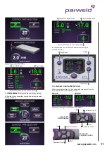
Page 11: ... setup Follow the screen prompts to complete the machine setup Example setting In manual mode you can adjust the parameters using the controls indicated Parameter Scroll Adjust Inductance short circuit current Adjust Inductance short circuit current Adjust Voltage Value Inductance Voltage Up Wire Speed Parameter Scroll Down Torch with OLED Display Up Parameter Scroll Down Parameter Scroll Torch wi...

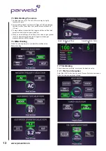
Page 12: ...e setup Example setting 7 5 MIG Welding Procedure 1 Position wire over joint The end of the wire may be lightly touching the work 2 Lower welding helmet operate torch trigger and begin welding Hold the torch so the contact tip to work distance is about 3 8 10 mm 3 To stop welding release the torch trigger and then pull the torch away from the work after the arc goes out 4 When no more welding is t...

Page 13: ...erial type and thickness with HF starting Auto Set Example 7 7 3 TIG Welding Set Up Follow the screen prompts to complete the machine set up Manual Set Example Adjust downslope and post flow to user preference using the knobs on the right of the screen 7 7 2 TIG Torch Installation See page 7 for Torch Connections to the Machine ...

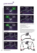
Page 14: ...ding Trigger Operation 2T 4T This toggles between 2 step and 4 step operation of the torch trigger In 2 step mode the trigger should be pressed and held down until the end of the weld In 4 step mode lower led the trigger is pressed and released to start and pressed and released to finish the weld In order to TIG weld one of these functions must be illuminated Not all functions are available in 2T ...

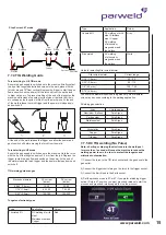
Page 15: ...mm 15 30 20 60 1 16 1 6mm 60 120 75 150 3 32 2 4mm 100 180 150 250 Tungsten electrode types Type Application Colour Thoriated 2 DC welding of mild steel Stainless steel and Copper Red Type Application Colour Ceriated 2 DC welding of mild steel Stainless steel Copper AC welding of aluminium magnesium and their alloys Grey Zirconiated AC welding of aluminium magnesium and their alloys White Guide fo...

Page 16: ...0s The value is displayed on the digital display B 2s is a good initial setting 14 Rotate the control knob to move the LED to the final current G This can be adjusted from 5 to 100 of the main welding current The value is displayed on the digital display B 10 is a good initial setting Note this function only operates in 4T switch mode 15 Rotate the control knob to move the LED to the Post Gas time...

Page 17: ...n the digital display B 3s is a good initial setting 16 Rotate the control knob to move the LED to the AC frequency I This can be adjusted from 25 to 200Hz dependant on the welding amperage The value is displayed on the digital display B 60hz is a good initial setting Increaseing the frequency has the effect of stiffening and focussing the arc making it good for welding close to threads or for cra...

Page 18: ...age than without pulse 50 150Hz really stiffen the arc and let you pinpoint the arc more than without pulse 0 5 10Hz reduce heat input the most The selected amperage and the consistency of travel speed can negate some of the effects of Power pulsing 7 8 Saving to Memory In any welding screen press the memory button From here you can see the last weld setting used O or select one of the memory loca...

Page 19: ...ifies Wrong gas Use welding grade shielding gas change to different gas Dirty welding wire Use clean dry welding wire Eliminate pickup of oil or lubricant on welding wire from feeder or liner Work piece dirty Remove all grease oil moisture rust paint coatings and dirt from work surface before welding Use a more highly deoxidizing welding wire contact supplier Welding wire extends too far out of no...

Page 20: ...Work piece dirty Remove all grease oil moisture rust paint undercoating and dirt from work surface before welding Insufficient shielding gas at welding arc Increase flow of shielding gas at regulator flow meter and or prevent drafts near welding arc Dirty welding wire Use clean dry welding wire Eliminate pickup of oil or lubricant on welding wire from feeder or liner Wire feed unit operates but no...

Page 21: ... plate b Welding current is too low c Wrong electrode angle d Travel speed of electrode is too high e Scale or dirt on joint surface a Use larger electrodes and preheat the plate b Increase welding current c Adjust angle so the welding arc is directed more into the base metal d Reduce travel speed of electrode e Clean surface before welding Description Possible cause Remedy Non metallic particles ...

Page 22: ...se from torch then raise gas pressure to blow out impurities e Turn on f Turn on g Increase electrode diameter or reduce the welding current Poor weld finish Inadequate shielding gas Increase gas flow or check gas line for gas flow problems Description Possible Cause Remedy Arc flutters during TIG welding a Tungsten electrode is too large for the welding current b Absence of oxides in the Weld poo...

Page 23: ...r 040 045 1 0mm 1 2mm x 4m B2524 50 Steel Liner 040 045 1 0mm 1 2mm x 5m B1536 30 Teflon Liner 023 035 0 6mm 0 9mm x 3m Liners Stock Code Description 1 B2506 Tip Adaptor M6 NI B2536 Tip Adaptor M8 See M8 Tips 2 B2502 Shroud Spring 3 B2501 Swan Neck 4 B1515 PG Handle Location Body 5 B1505 Lock Nut 6 B8015 Cable Support c w Knuckle Joint 7 B1521 Cable Terminal 8 B8514 MC4 Pro Grip Control Handle Kit...

Page 24: ...ct resistance and clarity Calibrated to operate at an inlet pressure of 30PSI Sensitive needle valve provides easy adjustment and the downward facing outlet connection eliminates hose kinking Fittings Fitted with standard 3 8 BSP inlet and outlet connections Stock Code Description 706101 Flow Meter Mixed Gas 25 lpm MIG 706100 Flow Meter 0 12 lpm TIG 10 0 Accessories 10 1 Feed Rolls 10 2 MIG Torch ...

Page 25: ...he above listed products are certified to be compliant with the RoHS directive with all homogeneous component parts being controlled to ensure material contents as per the list below Cadmium 0 01 by weight Lead 0 1 by weight Mercury 0 1 by weight Hexavalent chromium 0 1 by weight Polybrominated biphenyl s pbbs 0 1 by weight Polybrominated diphenyl ethers pbdes 0 1 by weight It should be noted that...

Page 26: ...mponents or parts of the product determined by Parweld to be defective Parweld makes no other warranty express or implied This warranty is exclusive and in lieu of all others including but not limited to any warranty of merchantability or fitness for any particular purpose Limitation of Liability Parweld shall not under any circumstances be liable for special indirect or consequential damages such...

Page 27: ...www parweld com 27 ...

Page 28: ...www parweld com Parweld Limited Bewdley Business Park Long Bank Bewdley Worcestershire England DY12 2TZ Tel 44 1299 266800 Fax 44 1299 266900 www parweld com info parweld co uk ...

Reviews: