64
C H A P T E R 5 R E P L A C I N G F I E L D R E P L A C E A B L E U N I T S ( F R U s )
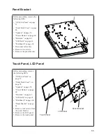
Mainboard Board
Before proceeding, remove the
following FRUs.
•
“SP-600-A Panel” on page
57.
•
“Panel Back Cover” on page
58.
•
“Heat Sink” on page 61.
•
“I/O Shield” on page 63.
1. Disconnect all cables from
the mainboard.
2. Remove four screws.
3. Remove the mainboard.
CAUTION
To avoid the thermal issue. When you replace the mainboard, check the
thermal pads should be stuck with the location marked on the panel
bracket.
Summary of Contents for SP-600-A
Page 1: ...POS Terminal SP 600 A Service Manual...
Page 2: ......
Page 8: ...vi...
Page 16: ...8 C H A P T E R 1 G E T T I N G S TA R T E D...
Page 45: ...37 4 When installation is completed click Finish...
Page 49: ...41 10 Click Next to continue 11 Click Next to continue...
Page 60: ...52 C H A P T E R 4 L O C AT I N G T H E P R O B L E M...
Page 74: ...66 C H A P T E R 5 R E P L A C I N G F I E L D R E P L A C E A B L E U N I T S F R U s...
Page 75: ...67 APPENDIX PART LIST AND SPECIFICATION Figure 6 1 Exploded diagram main parts...
Page 77: ...69 Figure 6 2 Exploded peripheral parts PM 116 VFD MSR...


