53
CHAPTER 5
REPLACING FIELD REPLACEABLE UNITS (FRUs)
This chapter provides instructions for replacing FRUs. The following topics are described.
•
Safety and precautions on the page 53
•
Before you begin on the page 54
•
Replacing parts on the page 54
•
MSR on the page 55
•
Customer Display on the page 55
•
HDD on the page 56
•
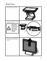
SP-600-A Panel on the page 57
•
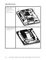
Panel Back Cover on the page 58
•
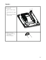
Speaker on the page 59
•
Power Button on the page 60
•
Heatsink on the page 61
•
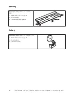
Memory on the page 62
•
Battery on the page 62
•
I/O Shield on the page 63
•
Mainboard Board on the page 64
•
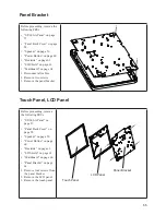
Panel Bracket on the page 65
•
Touch Panel, LCD Panel on the page 65
Only qualified personnel should perform repairs on the SP-600-A. Dam
-
age due to unauthorized servicing is not covered by the warranty.
Safety and precautions
Computer components and electronic circuit boards can be damaged by discharges of static electricity.
Working on computers that are still connected to a power supply can be extremely dangerous. Follow these
guidelines to avoid damage to the computer or injury to yourself.
•
Always disconnect the unit from the power outlet.
•
Leave all components inside the static-proof packaging that they ship with until they are ready for
installation.
•
After replacing optional devices, make sure all screws, springs, or other small parts are in place and
are not left loose inside the case. Metallic parts or metal flakes can cause electrical shorts.
If the LCD breaks and fluid gets onto your hands or into your eyes, im
-
mediately wash with water and seek medical attention.
CAUTION
CAUTION
Summary of Contents for SP-600-A
Page 1: ...POS Terminal SP 600 A Service Manual...
Page 2: ......
Page 8: ...vi...
Page 16: ...8 C H A P T E R 1 G E T T I N G S TA R T E D...
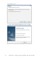
Page 45: ...37 4 When installation is completed click Finish...
Page 49: ...41 10 Click Next to continue 11 Click Next to continue...
Page 60: ...52 C H A P T E R 4 L O C AT I N G T H E P R O B L E M...
Page 74: ...66 C H A P T E R 5 R E P L A C I N G F I E L D R E P L A C E A B L E U N I T S F R U s...
Page 75: ...67 APPENDIX PART LIST AND SPECIFICATION Figure 6 1 Exploded diagram main parts...
Page 77: ...69 Figure 6 2 Exploded peripheral parts PM 116 VFD MSR...


