Page 10
CameraMan
®
1-CCD Presenter Camera System Installation and Operations Manual • © 1999 ParkerVision, Inc.
Configuring the Tracking System Keypad
Tracking System Keypad
Check the
KEYPAD ADDRESS
rotary switch in the battery compartment of the keypad and
verify that the selected setting corresponds to the setting of the
BASE UNIT ADDRESS
switch
on the back of the autoTRACK Camera. If they are different, then adjust them to match.
For more information on configuring the
BASE UNIT ADDRESS
on the camera and
keypad, see the Installation and Operations Manual that came with the camera.
If the Tracking System Keypad is being used in the wireless RF mode:
1. Install the supplied AA batteries in the Tracking System Keypad by removing the
battery door and inserting the batteries into the battery compartment, as indicated.
2. Once the batteries are installed, replace the battery door and press one of the pan keys.
3. Verify that the LED on the front of the keypad illuminates. This indicates that the
batteries are installed properly.
If the LED does not illuminate, then the batteries may be installed backward.
Reverse the way the batteries are inserted and try again.
If the batteries are inserted improperly, it will not damage the keypad, the
keypad simply will not work.
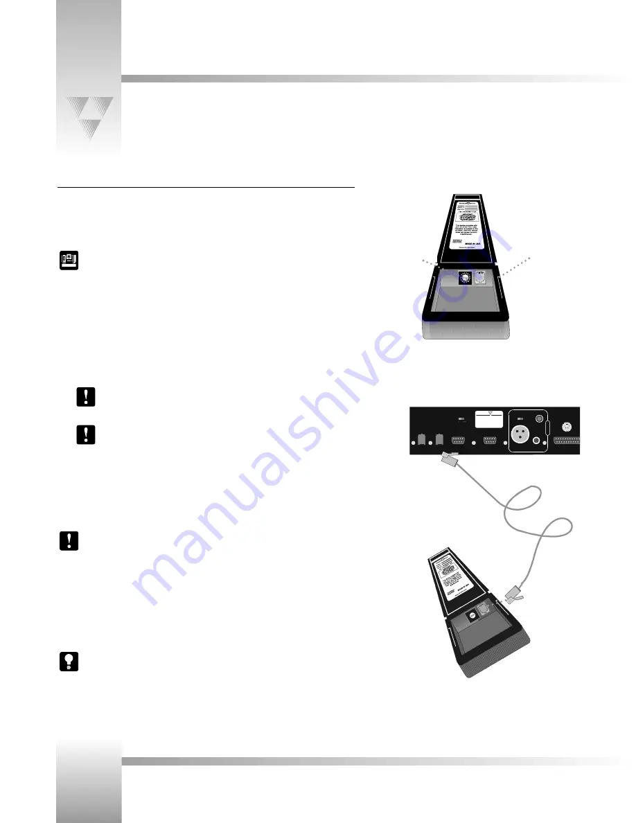
If the Tracking System Keypad is being used in the hard-wired mode, connect one end of the
CameraMan Keypad Cable to the RJ-11 type jack located in the battery compartment of the
Tracking System Keypad. Connect the other end of the cable to the Main Docking Station jack
labeled PVI Com.
Remove the batteries installed in the Tracking System Keypad when it is being used in
the hard-wired mode.
Press the
PAN
and
TILT
arrows (one at a time) and verify that the camera is responding to the
keypad. The
COM
LED on the front of the camera should flash with every command received
by the camera. If the autoTRACK LED on the front of the camera is not illuminated, then press
one of the four autoTRACK View buttons on the keypad. This should cause the autoTRACK
LED to begin flashing.
Refer to pages 15 through 22 for details on using the Tracking System Keypad.
Keypad Address
Battery
compartment
ANTENNA 2
S-VIDEO
OUT
C
RF CHANNEL
TO CAMER
A
U
D
I
O
LINE
MIC
BALANCED
U
NB
ALANCE
D
RS-485
OUT
PVI
COM
RS-232
AUX. A
LEVEL
-
+
P
ARKER ISION
®
Made in USA
0
1
2
3
4 5
67 8
9
A
B
C
DE
F
Tracking System Keypad
in hard-wired mode


