background image

HY13-1526-001-M1/US

Torqmotor™ Service Procedure

TC, TS, TB, TE and TJ Series

Parker Hannifin Corporation

Hydraulic Pump/Motor Division

Greeneville, TN 37745  US

33

Remove & 
inspect
coupling shaft

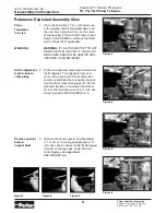
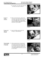
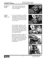
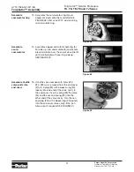
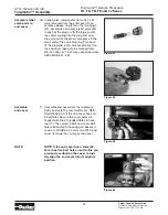
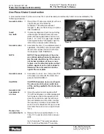
16.  Remove coupling shaft (10), by pushing on 

the output end of shaft. SEE FIGURE 26 & 
27. Inspect coupling shaft bearing and seal 
surfaces for spalling, nicks, grooves, severe 
wear or corrosion and discoloration. Inspect 
for damaged or worn internal and external 
splines or keyway. SEE FIGURE 28. Replace 
coupling shaft if any of these conditions exist.

NOTE

NOTE


NOTE: Minor shaft wear in seal area is 
permissible. If wear exceeds .020 inches 
(0.51 mm) diametrically, replace  
coupling shaft.


NOTE: A slight “polish” is permissible in 
the shaft bearing areas. Anything more 
would require coupling shaft replace-
ment.

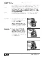
Inspection Areas

Inspect
housing
assembly

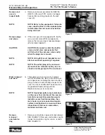
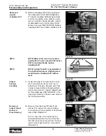
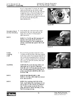
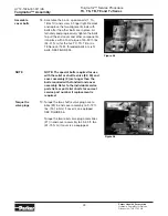
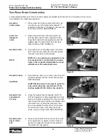
17.  Inspect housing (17) assembly for cracks, 

the machined surfaces for nicks, burrs, 
brinelling or corrosion. Remove burrs that 
can be removed without changing dimen-
sional characteristics. Inspect tapped holes 
for thread damage. SEE FIGURE 29. If the 
housing is defective in these areas, discard 
the housing assembly.

Figure 26

Figure 27

Figure 28

Figure 29

Disassembly and Inspection

Figure 30

Remove & 
inspect thrust 
washer & 
thrust bearing

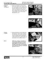
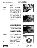
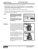
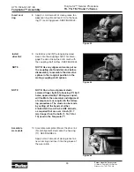
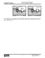
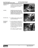
18.  Remove thrust bearing (12) and thrust 

washer (13). Inspect for wear, brinelling, 
corrosion and a full complement of retained 
rollers. SEE FIGURE 30. 


The TJ series has a thrust bearing (12) 
sandwiched between two thrust washers 
(13) that cannot be removed from the hous-
ing (17) unless bearing (14) is removed for 
replacement. 

Summary of Contents for Torqmotor TC Series

Page 1: ...HY13 1526 001 M1 US Torqmotor Service Procedure Effective January 2017 TC TS TB TE and TJ Series Low Speed High Torque Hydraulic Torqmotors ...

Page 2: ...catalog Due to the variety of operating conditions and applications for these products or systems the user through its own analysis and testing is solely responsible for making the final selection of the products and systems and assuring that all performance safety and warning requirements of the application are met The products described herein including without limitation product features specif...

Page 3: ...resent accurate clear and complete information and instructions regarding the techniques and tools required for maintaining repairing and servicing the complete line of Parker TC TS TB TE and TJ Torqmotor Units However despite the care and effort taken in preparing this general Service Manual Parker makes no warranties that a the Service Manual or any explanations illustrations information techniq...

Page 4: ...t Torqmotor Design Features Torqmotor TB TC Series features include The roller vane rotor set design offers a low friction wear compensation which maximizes the useful performance life of the motor Zero leak commutation valve provides greater more consistent volumetric ef ficiency Design flexibility TB offers the widest selection of shaft options displacements and mounting flanges in the industry ...

Page 5: ...rque and speed A unique high pressure shaft seal that elimi nates the need for case drains Up to 13 horsepower output Torqmotor TJ Series features include The roller vane rotor set design offers a low friction wear compensation which maximizes the useful performance life of the motor Zero leak commutation valve provides greater more consistent volumetric effi ciency Patented 60 40 spline member ar...

Page 6: ...n detail the procedure you should follow Column 3 illustrates this procedure with pho tographs Read all material carefully and pay special attention to the notes cautions and warnings A page with the Torqmotor exploded assembly view is provided several places in this manual The compo nent part names and item numbers assigned on this exploded assembly view correspond with names and item numbers in ...

Page 7: ...arts or slipping belts Hydraulic Components If you think the problem is caused by a hydraulic com ponent start by checking the easy to reach items Check all hoses and lines for cracks hardening or other signs of wear Reroute any usable hoses that are kinked severely bent or that rest against hot engine parts Look for leaks especially at couplings and fittings Replace any hoses or lines that don t ...

Page 8: ...or leakage 3 Severely worn or damaged internal splines 4 Excessive heat a Check for faulty relief valve and adjust or replace as required b Check for and repair worn pump c Check for and use correct oil for temperature of operation Replace worn rotor set by disassembling Torqmotor unit Replace rotor set drive link and coupling shaft by disassembling Torqmotor unit Locate excessive heat source usua...

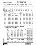
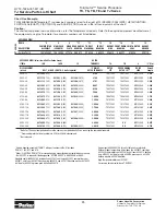
Page 9: ...andrel for TC TS TB TE Torqmotors SEE FIGURE 1 Feeler gage 005 inch 13 mm TC TS TB TE Torqmotors require blind hole bearing puller for 1 06 inch 26 9 mm and 1 62 inch 41 1 mm diameter bearing bushing TJ requires blind hole bearing puller for 1 400 inch diameter 35 6 mm and 2 130 inch diameter 5 41 mm bearing Clean corrosion resistant grease Part 406018 is included in each seal kit Recommended grea...

Page 10: ... 70 2 235 56 77 585 14 86 2 483 63 07 595 15 11 2 485 63 12 660 16 76 2 500 63 5 675 17 15 2 88 73 2 1 058 26 87 Torque Chart Part Name Item Number Torque bolt 5 16 24 UNF 2A 1 1A 1B or 1C 25 30 ft lbs 33 40 N m bolt 5 8 18 UNF 2A 10D 140 180 ft lbs 190 244 N m nut 3 4 16 UNF 2B 27A TC TB TE 175 255 ft lbs 237 305 N m Castle nut 1 20 UNEF 2B 27A TJ 300 400 ft lbs 407 542 N m Fabricate if considere...

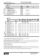
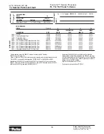
Page 11: ...st Washer TJ Series Qty 2 14 Shaft Seal Item No Description 15 Back Up Washer 16 Back Up Ring 17 Housing 18 Steel Bushing 19 Dirt Water Seal 20 O Ring 2 21 Plug 2 22 Relief Valve 2 23 Plug 2 24 Shuttle Valve 25 Spring 2 26 Key 27a Castle Nut 27b Patch Nut MATCHED SET REAR PORT OPTION COMPONENTS ASSEMBLE WITH WEDGE SIDE OF COMMUTATOR SEAL DOWN INTO COMMUTATOR FACE TORQUE TO 25 30 FT LBS 34 41 Nm 6 ...

Page 12: ...HY13 1526 001 M1 US Torqmotor Service Procedure TC TS TB TE and TJ Series Parker Hannifin Corporation Hydraulic Pump Motor Division Greeneville TN 37745 US 12 ...

Page 13: ...o can cause problems when the mo tor is painted To correct this problem we have re positioned the section O ring grooves on five of the six parts all but the front housing so that the O ring grooves are all facing up during assembly It will now be pos sible to install the O rings dry eliminating the problem The part numbers of the five re designed parts will change but the complete model number TE...

Page 14: ...ker Hannifin Corporation Hydraulic Pump Motor Division Greeneville TN 37745 US 14 1 2 4 5 6 7 8 17 TC TB TE and TJ Assembly before July 1 2012 MADE IN USA 18212 No seal groove Seal groove Seal groove both faces Seal groove bottom face only Torqmotor Exploded View No seal groove ...

Page 15: ... 1 2 4 5 6 7 8 17 TC TB TE and TJ Assembly on or after July 1 2012 Torqmotor Exploded View MADE IN USA 18312 Item QTY New Part Old Part Description 8 1 477376 477341 Wear Plate 7 1 TE127003 MF127003 Rotor Set 6 1 TE015000 MF015000 Manifold 4 5 1 TE018000A1 MF018000A1 Commutator Assembly 2 1 TE016000 MF016007 End Cover No seal groove Seal groove top face only ...

Page 16: ...eries Assembly before July 1 2012 Torqmotor Exploded View MADE IN USA 18212 Item No Description 1 Special Bolt 6 2 End Cover 3 Seal Ring Commutator 4 Seal Ring 5 5 6 Commutator Assembly Matched Set 7 Manifold 8A Rotor Set Matched Set Item No Description 9 Wear Plate 10 Drive Link 12 Coupling Shaft 12A Stainless Key 13 Steel Bushing 14 Thrust Washer 15 Thrust Bearing 16 Shaft Seal Item No Descripti...

Page 17: ...ies Assembly on or after July 1 2012 Torqmotor Exploded View MADE IN USA 18312 Item No Description 1 Special Bolt 6 2 End Cover 3 Seal Ring Commutator 4 Seal Ring 5 5 6 Commutator Assembly Matched Set 7 Manifold 8A Rotor Set Matched Set Item No Description 9 Wear Plate 10 Drive Link 12 Coupling Shaft 12A Stainless Key 13 Steel Bushing 14 Thrust Washer 15 Thrust Bearing 16 Shaft Seal Item No Descri...

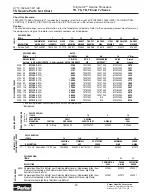
Page 18: ...Item Bolt Per Option Group ITEM 1 OR 1A OR 1C ROTOR THICKNESS 7A 7B 9 L Dim DISPLACEMENT in3 rev BOLT BOLT LENGTH 5 bolts required L DIM OF ROTOR THICKNESS ROTOR SET FREE RUNNING ROTOR SET DRIVE LINK Overall Length 0036 2 2 021356 2 625 2750 TE017003 TE017005 MF013000 2 975 0045 2 7 021311 2 750 021443 3 440 021308 3 875 3169 TE027003 TE027005 MF023000 3 021 0050 3 0 021311 2 750 021444 3 500 0213...

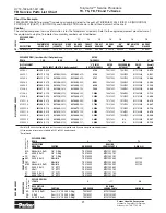
Page 19: ...on Resistant Paint Item 1 032435 032821 032377 AAAH Fluorocarbon Seals Item 1 032435 032822 032809 BBCK 1740 PSI Internal Bidirectional Item 1C TE016006A7 032435 032821 032377 411068A1 032750 401660 4100107 Relief No Paint BBCM 1200 PSI Internal Bidirectional Item 1C TE016006A31 032435 032821 032377 411068A1 032750 401660 41001031 Relief No Paint BBCN 2030 PSI Internal Bidirectional Item 1C TE0160...

Page 20: ... 750 3751 TE037003 TE037005 MF033000 3 080 0065 4 0 021306 2 875 5001 TE047003 TE047005 MF043000 3 206 0080 5 0 021382 3 000 6258 TE057003 TE057005 MF053000 3 334 0100 6 0 021357 3 125 7508 TE067003 TE067005 MF063000 3 460 0130 8 0 021307 3 375 1 0008 TE087003 TE087005 MF083000 3 712 0165 9 9 021358 3 625 1 2508 TE107003 TE107005 MF103000 3 969 0195 11 9 021308 3 875 1 5008 TE127003 TE127005 MF123...

Page 21: ...ear 3 4 16 SAE O Ring TE016001 MF012010A2 BR SAE B 2 Bolt Rear 3 4 16 SAE O Ring TE016001 MF012076A2 REAR PORTING Mounting Code Porting Code FRONT PORTING DISPLACEMENT GROUP EXPLODED VIEW Select Item Bolt Per Option Group ROTOR ITEM 1 OR 1A OR 1C THICKNESS 7A 7B 9 L Dim DISPLACEMENT in3 rev BOLT BOLT LENGTH 5 bolts required L DIM OF ROTOR THICKNESS ROTOR SET FREE RUNNING ROTOR SET DRIVE LINK Overa...

Page 22: ...eals Item 1 032435 032822 032809 BBCK 1740 PSI Internal Bidirectional Item 1C TE016006A7 032435 032821 032377 411068A1 032750 401660 4100107 Relief No Paint BBCM 1200 PSI Internal Bidirectional Item 1C TE016006A31 032435 032821 032377 411068A1 032750 401660 41001031 Relief No Paint BBCN 2030 PSI Internal Bidirectional Item 1C TE016006A5 032435 032821 032377 411068A1 032750 401660 4100105 Relief No...

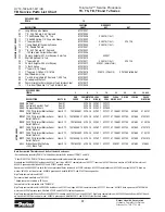
Page 23: ...rt 3 4 16 SAE O Ring TE016001 MF012021A1 UR Small Wheel Mount Rear Port 3 4 16 SAE O Ring TE016001 MF012009A1 N A 455063 FR 4 Bolt Mount Rear Port 3 4 16 SAE O Ring TE016001 MF012010A1 AR SAE A 2 Bolt Rear Port 3 4 16 SAE O Ring TE016001 MF012008A1 N A 455063 NOTE Rear ported TE motors always have 5 bolts at the back end cover HOUSING GROUP Mounting Code Porting Code REAR PORTING FRONT PORTING Mou...

Page 24: ...06A7 N A BBCM 1200 PSI Internal Bidirectional Relief No Paint Item 1C TE016006A31 N A BBCN 2030 PSI Internal Bidirectional Relief No Paint Item 1C TE016006A5 N A BBCP 1450 PSI Internal Bidirectional Relief No Paint Item 1C TE016006A10 N A BBCT 1560 PSI Internal Bidirectional Relief No Paint Item 1C TE016006A2 N A AAJV Bidirectional Shuttle Valve 3 30 Black Paint Item 1A TE016003A1 N A 032435 03282...

Page 25: ...06018 grease pack 029118 backup washer 050016 bulletin High Temp commutator seal 032861 For reverse timed manifold use TE015001 EXPLODED VIEW Select Item Bolt Per Option Group ROTOR ITEM 1 OR 1A OR 1C THICKNESS 7A 7B 9 L Dim DISPLACEMENT in3 rev BOLT BOLT LENGTH 6 bolts required L DIM OF ROTOR THICKNESS ROTOR SET FREE RUNNING ROTOR SET DRIVE LINK Overall Length 0036 2 2 021356 2 625 2750 TE017003 ...

Page 26: ...ld use TE015001 EXPLODED VIEW ITEM 2 1 1A 1C 2 4 3 14 END COMMUTATOR SEAL INNER DESCRIPTION BOLT COVER SEAL RING 5 SEAL AAAB No Paint ITEM 1 TE016000 032435 032821 032817 AAAC Corrosion Resistant Paint ITEM 1 TE016000 032435 032821 032817 AAAG Fluorocarbon Seals ITEM 1 TE016000 032435 032822 032818 AABJ Free Running Rotor Set ITEM 1 TE016000 032435 032821 032817 BBCK 1740 PSI Internal Bidirectiona...

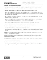
Page 27: ... around fittings and hose connections before disconnect ing and removing the Torqmotor Remove rust or corrosion from coupling shaft Remove coupling shaft connections and hose fittings and immediately plug port holes and fluid lines Remove the Torqmotor from system drain it of fluid and take it to a clean work surface Clean and dry the Torqmotor before you start to disassemble the unit As you disas...

Page 28: ...THE SERVICE PRO CEDURES CAUSING INJURY Scribe alignment mark loosen valve plugs 2 Scribe an alignment mark down and across the Torqmotor components from end cover 2 to housing 17 to facilitate reas sembly orientation where required Loosen two shuttle or relief valve plugs 21 23 for disassembly later if included in end cover 3 16 or 3 8 inch Allen wrench or 1 inch hex socket required SEE FIGURES 4 ...

Page 29: ...cluded in seal kits but serviced separately if required NOTE The orifice plug in the end cover 2 must not be removed as they are ser viced as an integral part of the end cover Wash inspect end cover NOTE 6 Thoroughly wash end cover 2 in proper solvent and blow dry Be sure the end cover valve apertures including the internal orifice plug are free of contamination Inspect end cover for cracks and th...

Page 30: ...nd commutator ring as a matched set SEE FIGURE 14 15 Remove manifold 9 Remove manifold seal ring 3 and discard SEE FIGURE 16 Remove the manifold 6 and inspect for cracks surface scoring bri nelling or spalling Replace manifold if any of these conditions exist SEE FIGURE 17 A polished pattern on the ground surface from commutator or rotor rotation is normal NOTE NOTE The manifold is constructed of ...

Page 31: ...tor set 7 components may become disassembled during service pro cedures Marking the surface of the rotor and stator that is facing UP with etching ink or grease pencil before removal from Torqmotor will ensure correct reassem bly of rotor into stator and rotor set into Torqmotor Marking all rotor compo nents and mating spline components for exact repositioning at assembly will en sure maximum wear...

Page 32: ... fine emery paper may be used SEE FIGURE 25 Remove any key 26 or nut 27a 27b Remove seal ring from housing 14 Remove and discard seal ring 3 from housing 17 SEE FIGURE 24 Figure 25 Figure 24 Figure 23 Figure 22 Disassembly and Inspection Remove inspect drive link 13 Remove drive link 9 from coupling shaft 10 if it was not removed with rotor set and wear plate Inspect drive link for cracks and worn...

Page 33: ...h is permissible in the shaft bearing areas Anything more would require coupling shaft replace ment Inspection Areas Inspect housing assembly 17 Inspect housing 17 assembly for cracks the machined surfaces for nicks burrs brinelling or corrosion Remove burrs that can be removed without changing dimen sional characteristics Inspect tapped holes for thread damage SEE FIGURE 29 If the housing is defe...

Page 34: ...1 If the bearings bushing or thrust washers must be replaced use a suitable size bear ing puller to remove bearing bushings 18 and 11 from housing 17 without damag ing the housing Remove thrust washer 13 and thrust bearing 12 if they were previ ously retained in the housing by bearing 11 SEE FIGURES 33 THE DISASSEMBLY OF TORQMOTOR IS COMPLETED Figure 31 Figure 31A Figure 31B Figure 31C Figure 32 F...

Page 35: ...EN USING ANY SOLVENT EVEN A SMALL EXPLOSION OR FIRE COULD CAUSE INJURY OR DEATH WARNING WEAR EYE PROTECTION AND BE SURE TO COMPLY WITH OSHA OR OTHER MAXIMUM AIR PRESSURE REQUIREMENTS Press in outer bearing bushing 1 If the housing 17 bearing components were removed for replacement thoroughly coat and pack a new outer bearing bushing 18 with clean corrosion resistant grease recommended in the mater...

Page 36: ...ION CAUTION Because the bearing bushings 11 and 18 have a press fit into the housing they must be discarded when removed They must not be reused Figure 37A Figure 37B Torqmotor Assembly Press in dirt water seal 2 Press a new dirt and water seal 19 into the housing 17 outer bearing counterbore The dirt and water seal 19 must be pressed in until its flange is flush against the housing SEE FIGURE 37A...

Page 37: ...cond thrust washer 13 in that order before pressing in the inner housing bearing 11 SEE FIGURES 40A 40B When these components are in place press new bearing 11 into the housing 17 to a depth of 03 inches 76 mm max for TJ below the housing wear plate contact face Use the opposite end of the bearing mandrel used to press in outer bearing 18 Refer ence Figure 2 in the Tools and Materials Required for...

Page 38: ... wash ers 13 and thrust bearing 12 SEE FIGURE 40D Figure 42 Figure 41 Figure 40D Torqmotor Assembly Install coupling shaft 7 Be sure that a generous amount of clean corrosion resistant grease has been applied to the lower outer housing bearing bushing 18 Install the coupling shaft 10 into hous ing 17 seating it against the thrust bearing 12 in TC TS TB and TE Series housings SEE FIGURE 42 CAUTION ...

Page 39: ...4 UNF 2A or 5 16 24 UNF 2A bolts as required that are over 5 inch 12 7 mm longer than the bolts 1 1A 1B or 1C used in the Torqmotor Figure 43 Figure 44 Figure 45 Torqmotor Assembly Install drive link NOTE 9 Install drive link 9 the long splined end down into the coupling shaft 10 and en gage the drive link splines into mesh with the coupling shaft splines SEE FIGURE 44 NOTE Use any alignment marks...

Page 40: ...and to maintain the original rotor drive link spline contact A rotor set without a counterbore and that was not etched before disassembly can be reinstalled using the drive link spline pattern on the rotor splines if apparent to determine which side was down Figure 46 Figure 47 Torqmotor Assembly NOTE The manifold 6 is made up of several plates bonded together perma nently to form an integral comp...

Page 41: ...new commutator seal ring 3 flat side up into commutator 5 and assem ble commutator over the end of drive link 9 onto manifold 6 with seal ring side up SEE FIGURE 49 Assemble shuttle valve parts into end cover 15 If shuttle valve components items 23 24 25 were removed from the end cover 2 turn a plug 23 with a new o ring 20 loosely into one end of the valve cavity in the end cover Insert a spring 2...

Page 42: ...d cover no longer has o ring section seal NOTE NOTE If the end cover has a valve 22 24 or has five bolt holes use the line you previously scribed on the cover to radi ally align the end cover into its original position Figure 51 Assemble relief valve parts in end cover 16 If relief valve components items 21 22 were removed from the end cover 2 as semble a new o ring 20 on the two plugs 21 Assemble...

Page 43: ... N m for the five TC TS TB or six TE Series 5 16 24 threaded bolts or six TJ bolts SEE FIGURE 55 Figure 56 Torqmotor Assembly NOTE NOTE The special bolts required for use with the relief or shuttle valve 22 24 end cover assembly 2 are longer than the bolts required with standard and cover assembly Refer to the individual service parts lists or parts list charts for correct service part number if r...

Page 44: ...OMPLETE EXCEPT FOR WOODRUFF KEY NUT WASHER BOLT LOCKWASHER RETAINER RING or PORT O RINGS AT INSTALLATION IF APPLICABLE PROCEED TO FINAL CHECKS SECTION Figure 57B TC TS TB TE Series Housing Thrust Washers Seal Shaft Thrust Bearing Backup W Steel Washer asher Not To Scale Torqmotor Assembly Figure 57A TJ Series Housing Thrust Washers Seal Shaft Thrust Bearing Backup Washer Steel Washer Not To Scale ...

Page 45: ... manifold side of the rotor was etched during Torqmotor disassem bly this side should be up If the rotor is not etched and does not have a coun terbore use the drive link spline contact pattern apparent on the rotor splines to determine the rotor side that must be against the wear plate Assemble vanes CAUTION Assemble full complement of vanes Remove two assembled bolts 4 Assemble six vanes or as m...

Page 46: ...ink 9 splines NOTE Use any marking you applied to rotor set components to reassemble the compo nents in their original relationship to ensure ultimate wear life and performance Assemble vanes CAUTION 4 Assemble six vanes or as many vanes that will readily assemble into the stator vane pockets SEE FIGURE 62 CAUTION Excessive force used to push the rotor vanes into place could shear off the coating ...

Page 47: ...must be reas sembled in their respective stator half for the rotor set to function properly Assemble vanes 8 Assemble six vanes or as many vanes that will readily assemble into the stator vane pockets SEE FIGURE 66 Assemble full complement of vanes 9 Grasp the output end of coupling shaft 10 with locking pliers or other appropriate turning device and rotate coupling shaft drive link and rotor to s...

Page 48: ... is for counter clockwise coupling shaft rotation Use test stand if available to check operation of the Torqmotor Hydraulic Fluid Keep the hydraulic system filled with one of the following 10W40 SE or SF manufacturers suggested oil Hydraulic fluid as recommended by equipment manufacturer but the viscosity should not drop below 50 SSU or contain less than 125 zinc anti wear additives CAUTION Do not...

Page 49: ...ate and correct any external leak in the hydraulic system no matter how minor the leak Comply with manufacturer s specifications for cleaning or replacing the filter CAUTION Do not weld braze solder or any way alter any Torqmotor component CAUTION Maximum operating pressure must not exceed recommended Torqmotor pressure capacity CAUTION Always carefully inspect any system component that may have b...

Page 50: ...HY13 1526 001 M1 US Torqmotor Service Procedure TC TS TB TE and TJ Series Parker Hannifin Corporation Hydraulic Pump Motor Division Greeneville TN 37745 US 50 Notes ...

Page 51: ... behalf all documents Seller deems necessary to perfect its security interest 11 Improper use and Indemnity Buyer shall indemnify defend and hold Seller harm less from any claim liability damages lawsuits and costs including attorney fees whether for personal injury property damage patent trademark or copyright infringe ment or any other claim brought by or incurred by Buyer Buyer s employees or a...

Page 52: ...Parker Hannifin Corporation 2745 Snapps Ferry Road Greeneville TN 37745 USA Tel 423 639 8151 FAX 423 787 2418 www parker com pumpmotor ...

Reviews: