


ENGLISH
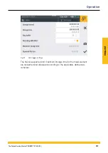
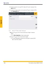
After selecting the
Trigger logic
measuring method, the device dis-
plays predefined parameters to complete the measurement.
1
Tap on the
button.
Ä
The configuration window opens in which to define the param-
eters.
2
Select a trigger and define the parameters trigger according to
your application.
The table below contains information on the triggers available:
Designation
Description
Keystroke
Measurement is started by tapping on the corre-
sponding button
Level
Measurement is started/stopped on exceeding or
dropping below a limit value
Window
Measurement is started/stopped on exceeding or
dropping below one of two limit values for a defined
measuring range
Time
Measurement is started/stopped at a defined mo-
ment of time
External
Measurement is started/stopped on transition of a
digital signal from High to Low
Measurement is started/stopped on transition of a
digital signal from Low to High
Channel
warning value
Measurement is started/stopped when defined
warning values occurs
Channel alarm
value
Measurement is started/stopped when defined
alarm values occur
Duration
Measurement stops after a defined time period has
expired
INFORMATION
Please note that the D-IN connection must be activated for the exter-
nal trigger. Refer to Chapter
&
"D-IN/D-OUT F1/F2" on Page 232.
214
The Parker Service Master CONNECT V1.0/04/20
Operation
Summary of Contents for Service Master CONNECT
Page 1: ...The Parker Service Master CONNECT Bedienungsanleitung Operating Manual ...
Page 107: ...DEUTSCH Abb 55 Gerät Device 107 The Parker Service Master CONNECT V1 0 04 20 Bedienung ...
Page 133: ...DEUTSCH 12 3 Maßzeichnungen 133 The Parker Service Master CONNECT V1 0 04 20 Anhang ...
Page 134: ...DEUTSCH 134 The Parker Service Master CONNECT V1 0 04 20 Anhang ...
Page 135: ...DEUTSCH 135 The Parker Service Master CONNECT V1 0 04 20 Anhang ...
Page 137: ...DEUTSCH 137 The Parker Service Master CONNECT V1 0 04 20 Anhang ...
Page 245: ...ENGLISH Fig 55 Device 245 The Parker Service Master CONNECT V1 0 04 20 Operation ...
Page 271: ...ENGLISH 12 3 Dimensional Drawings 271 The Parker Service Master CONNECT V1 0 04 20 Appendix ...
Page 272: ...ENGLISH 272 The Parker Service Master CONNECT V1 0 04 20 Appendix ...
Page 273: ...ENGLISH 273 The Parker Service Master CONNECT V1 0 04 20 Appendix ...
Page 275: ...ENGLISH 275 The Parker Service Master CONNECT V1 0 04 20 Appendix ...


