GENERAL THEORY
Note: Before July, 1st 2015
3.5
OPERATIONAL DESCRIPTION:
Figure 3.2: Water Quality Monitor - Panel View.
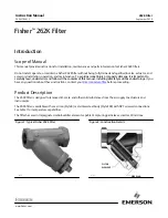
Figure 3.3: Master Control Center - Panel View.
Figure 3.4: Optional Remote Control Center
–
Panel View.
Figure 3.5:
Product Solenoid Valve.
PRODUCT WATER MONITORING SYSTEM
The product water (or permeate) flows past a conductivity sensor which provides a signal to the water
quality monitor. Depending on the concentration of total of dissolved solids (TDS) in the permeate, the
following occurs:
If the permeate TDS is detected
AT GREATER
than 500 parts per million (ppm), indicating
POOR
quality water), a signal is sent from the water quality monitor (Figure 3.2), to the product diversion valve
(Figure 3.5) to reroute the (high salinity) water away from your water storage tank(s) and into the reject
stream.
If the permeate TDS has
LESS
than 500 ppm, indicating
GOOD
(drinking) water, a signal is sent to the
product diversion valve to redirect the good permeate through the product flowmeter and finally into
your water storage tank(s).
MASTER CONTROL CENTER
The Master Control Center (MCC) provides centralized control and monitoring of all important unit
functions and operating parameters (Figure 3.3). This is achieved through the use of a fully integrated
package of control pushbuttons and alarm/status lights, as well as an easy to read Message Display
console.
REMOTE CONTROL CENTER (OPTIONAL)
ppm/NaCl
ppm/NaCl
Summary of Contents for Pure Water Series
Page 2: ......
Page 3: ...THE PURE WATER SERIES 400 2000 GPD USER GUIDE REFERENCE MANUAL ...
Page 4: ......
Page 7: ......
Page 9: ......
Page 62: ...TROUBLESHOOTING Figure 8 0 Troubleshooting Flow Diagram T ...
Page 63: ...TROUBLESHOOTING Figure 8 0 Troubleshooting Flow Diagram CONTINUED T ...
Page 64: ...DRAWINGS AND DIAGRAMS 38 VMT v JUNE 2008 9 0 DRAWINGS AND DIAGRAMS ...
Page 65: ......
Page 66: ......
Page 67: ......
Page 75: ......
Page 76: ......
Page 77: ......
Page 78: ......
Page 79: ......
Page 80: ......
Page 81: ......
Page 82: ......
Page 83: ......
Page 84: ......
Page 85: ......
Page 86: ......
Page 87: ......
Page 88: ......
Page 89: ......
Page 90: ......
Page 91: ...PARTS REFERENCE 62 VMT v JUNE 2008 Drawing upgrade as of 4 1 2015 ...
Page 92: ......
Page 93: ......
Page 94: ......
Page 95: ......
Page 96: ......
Page 97: ......
Page 98: ......
Page 99: ......
Page 100: ......
Page 101: ......
Page 102: ......
Page 103: ......
Page 104: ...PARTS REFERENCE 39 VMT v JUNE 2008 10 0 PARTS REFERENCE ...
Page 105: ......
Page 106: ......
Page 107: ......
Page 108: ......
Page 109: ......
Page 110: ......
Page 111: ......
Page 112: ......
Page 113: ......
Page 114: ......
Page 115: ......
Page 116: ......
Page 117: ......
Page 118: ......
Page 119: ......
Page 120: ......
Page 121: ......
Page 122: ......
Page 123: ......
Page 124: ...MANUFACTURER S LITERATURE 92 VMT v JUNE 2008 Drawing upgrade as of 4 1 2015 ...
Page 135: ...MANUFACTURER S LITERATURE 40 VMT v JUNE 2008 11 0 MANUFACTURER S LITERATURE ...
Page 136: ......
Page 165: ...708 Series High Pressure Titanium Positive Displacement Pump 26 ...
Page 166: ...708 5 DRAWINGS ...