background image

User Guide 


Quick Start Guide 


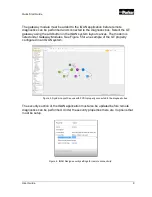
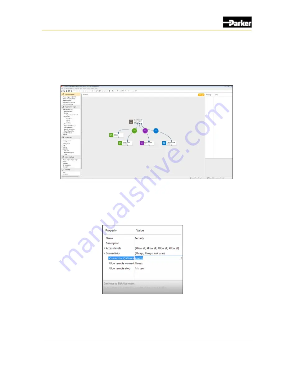
The gateway module must be added to the IQAN application before remote 
diagnostics can be performed and connected to the diagnostic bus. Select the GT 
gateway using the add button in the IQAN system layout canvas. The modem is 
listed under Gateway Modules. See Figure 5 for an example of the GT properly 
configured in an IQAN system. 


Figure 5. System Layout Canvas with PVSG properly connected to the diagnostic bus 

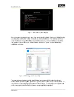
The security section of the IQAN application must also be updated before remote 
diagnostics can be performed. Under the security properties there are 3 options that 
must be setup. 


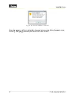
Figure 6. IQAN Design security settings for remote connectivity.


Summary of Contents for PSVG-IQAN-C2E1M1W1U1

Page 1: ...Parker Vehicle System Gateway for Mobile Equipment with IQAN Integration PSVG IQAN C2E1M1W1U1 User Guide UG PVSG IQAN C2E1M1W 1U1 1017 001...

Page 2: ...and testing is solely responsible for making the final selection of the system and components and assuring that all performance endurance maintenance safety and warning requirements of the applicatio...

Page 3: ...rt Numbers 4 2 Quick Start Guide 5 2 1 Getting Started using the Web Application for Remote Monitoring 5 2 1 1 Requisite Information 5 2 1 2 Logging in and Creating the Asset 6 2 2 Getting Started wit...

Page 4: ...ting 28 8 1 Status LEDs 28 8 2 Troubleshooting 29 8 2 1 Users gateway will not connect to a cellular network 29 8 2 2 IQAN Connect remote diagnostics will not connect 30 8 2 3 Users gateway is connect...

Page 5: ...de to this document over the course of its publication history Release Date Description of Change Rev 001 5 18 2018 First release of this document Rev 002 6 18 2018 Updated URL s Added System Block Di...

Page 6: ...quipment or degradation of signal When you see these symbols follow the instructions carefully and proceed with caution General safety regulations Work on the hydraulics control electronics may only b...

Page 7: ...rol system 1 Disconnect the electrical connections between the system and external equipment 2 Disconnect the negative cable from the battery 3 Disconnect the positive cable from the battery 4 Connect...

Page 8: ...been verified Do not start the machine if anyone is near the machine Safety during maintenance and fault diagnosis Before performing any work on the hydraulics control electronics ensure that The mac...

Page 9: ...oice of the Machine cloud the end to end solution also has a number of remote monitoring capabilities Integrates with any system utilizing J1939 canbus communication Capture log and transmit CANBUS in...

Page 10: ...ely connect to a vehicle enabling the following functionality over the air View live vehicle data for trouble shooting issues Remotely via cellular connection can eliminate a trip to the vehicle by a...

Page 11: ...of the PVSG IQAN hardware are listed in the following table PVSG IQAN C2E1M1W1U1 Characteristic Description Status LEDs 4 x tri color Communication CAN x 2 Modem x 1 Wi Fi x 1 Inputs 1 x Power Control...

Page 12: ...s remote monitoring and 250 MB per month of data 164632 3 Year production part This part number includes a 3 year contract for remote diagnostics remote monitoring and 250 MB per month of data 164633...

Page 13: ...e IQAN Connect cloud The knowledge base can be found at https parkeriot atlassian net wiki x RoJ6E 2 1 1 Requisite Information You must have the following information available to create your asset in...

Page 14: ...the user must log into the web portal with their credentials The web portal can be accessed at https parkermobileiot com After the user has logged into their organization they will be greeted with th...

Page 15: ...rganization As you begin typing it will narrow the list The nickname is a configurable field that can be edited at any time Serial number is a configurable field that can be edited at any time we reco...

Page 16: ...IQAN Connect service subscription Gateway installed per Section 3 of the guide Gateway connected to diagnostic bus of the IQAN system Before starting your remote connection ensure the gateway is powe...

Page 17: ...s The modem is listed under Gateway Modules See Figure 5 for an example of the GT properly configured in an IQAN system Figure 5 System Layout Canvas with PVSG properly connected to the diagnostic bus...

Page 18: ...l connect immediately Danger Risk of death or injury Ensure that the vehicle is in a safe state before performing remote diagnostics or program updates The user can remotely connect with both IQAN Des...

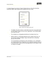
Page 19: ...you access it An example of the window is shown in Figure 4 note Master tag I1GDENN is online The user choses the asset they would like to connect to and clicks the connect button While performing th...

Page 20: ...2E1M1W1U1 Quick Start Guide Once the system confirms connection the user can use any of the diagnostic tools as if they were plugged directly into the back of the module Figure 9 Connection establishe...

Page 21: ...ommended that the gateway is mounted inside the cab of the vehicle The following guidelines are related to physically attaching the PVSG IQAN to a vehicle Secure the PVSG IQAN with bolts in all bolt h...

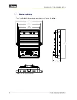
Page 22: ...ounting the PVSG IQAN to a Vehicle 3 1 Dimensions The PVSG IQAN dimensions are shown in Figure 10 below 5 25 5 84 4 69 1 61 6 30 Figure 10 PVSG IQAN dimensions 5 84 148 5 mm 5 25 133 5 mm 4 69 119 mm...

Page 23: ...product connector are covered in the connector manufacturer s datasheet Wire diameters used should be sufficient for the expected module current To use the remote diagnostic features of the PVSG IQAN...

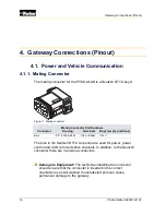
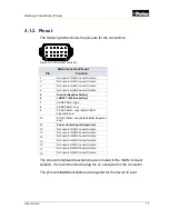
Page 24: ...mpty positions Main DT16 18SA K004 1062 16 0644 114017 The pins in the Deutsch DT16 connector are used for power power control and CAN communication channels In addition to the Deutsch connector there...

Page 25: ...8 CAN0 CANA Low 9 CAN1 CANB High default IQAN diagnostic bus 10 CAN1 CANB Low default IQAN diagnostic bus 11 Power Control Input Keyswitch 12 Not used in IQAN Connect Solution 13 Not used in IQAN Conn...

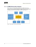
Page 26: ...Block Diagram When utilizing the PVSG IQAN gateway with an IQAN based control system it is very important to connect the diagnostic bus of the gateway to the diagnostic bus of the IQAN Master Control...

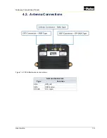
Page 27: ...User Guide 19 Gateway Connections Pinout 4 2 Antenna Connections Figure 14 PVSG IQAN antenna connections Antenna Connectors Type Function SMA GPS left SMA GSM center RP SMA Wi Fi right...

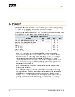
Page 28: ...Pin 6 of the module be connected directly to the vehicle battery source and to utilize Pin 11 Power Control for activating and deactivating as well as allowing a safe shut down sequence of the module...

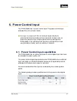
Page 29: ...r Control input capabilities The PVSG IQAN has an active high power control digital input that must be activated to power up the unit The power control digital input activates the PVSG IQAN when switc...

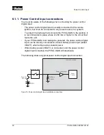
Page 30: ...e of 200 mA or higher in the circuit that feeds the unit If your PVSG IQAN must always be powered the power control digital input can be directly connected to a fused battery power input called VBATT...

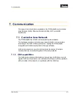
Page 31: ...N communication according to the SAE J1939 specification making the PVSG IQAN compatible with CAN based protocol through software CAN communication is used to communicate the status of multiple module...

Page 32: ...elements that are required for a J1939 CAN connection CAN Cable A shielded twisted pair cable should be used when connecting multiple modules to the CAN bus The cable for the J1939 CAN bus has three w...

Page 33: ...to one point on the network If grounded to multiple points a ground loop may occur CAN Stubs The CAN stubs cannot be longer than 1 meter and each stub should vary in length to eliminate bus reflection...

Page 34: ...uplink 21 1Mb s downlink or 5 76Mbps uplink 7 2Mb s downlink GSM 2G GSM 850 900 1800 1900 Mhz 3GPP Release PBCCH support GPRS 2G Class 12 CS1 CS4 up to 86 5 kbps EDGE 2 5G Class 12 MCS1 9 up to 236 8...

Page 35: ...WiFi interface Parameter Description Standard 802 11 b g n 2 4GHz Channels see note 1 1 13 Operational modes APN Client Concurrent two simultaneous instances Data transfer rate b 11 5 5 2 1 Mbps g 54...

Page 36: ...Ds are listed in the following tables Status LED Pattern Description Red solid Indicates error also read during programing Blue heartbeat Gateway booting in process of establishing connection Red hear...

Page 37: ...gateway to ensure the application of the gateway is correct If any of the steps do not solve the issue that the user is experiencing please contact support 8 2 1 Users gateway will not connect to a c...

Page 38: ...nc up with the changes made in the cloud Check to ensure that the CAN networks are properly wired per section 4 1 Check to ensure that the CAN networks are broadcasting the signal that the user attemp...

Page 39: ...ure the correct antenna lead is attached to the GPS connection Check for cable breaks and loose connections If the gateway is transmitting other signals but not GPS add the GPS mode to the template in...

Page 40: ...sired operation Any changes or modifications not expressly approved by the manufacturer could void the user s authority to operate the equipment The external antenna s used for this module must provid...

Page 41: ...ired operation Le pr sent appareil est conforme aux CNR d Industrie Canada applicables aux appareils radio exempts de licence L exploitation est autoris e aux deux conditions suivantes 1 l appareil ne...

Page 42: ...34 PSVG IQAN C2E1M1W1U1 Markings Approvals 9 3 EU Declaration of conformity...

Page 43: ...User Guide 35 Markings Approvals...

Page 44: ...N C2E1M1W1U1 Environmental specifications The following specifications apply to the PVSG IQAN IP Rating IP67 Operating Temperature 40 C to 70 C 1 Storage Temperature 40 C to 85 C 10 Environmental spec...

Page 45: ...m conventions The following symbols are used in the schematic diagrams in this document Symbol Meaning General input General output Frequency input Analog input Frequency sensor Pulse sensor Resistive...

Page 46: ...38 PSVG IQAN C2E1M1W1U1 Appendix Symbol Meaning Application switch Load Pull down resistor Pull up resistor Battery Fuse Resistor Ground Chassis ground...

Page 47: ......

Page 48: ...HY33 5027 IB US...

Reviews: