English
18/20
PSE 325-1000 60Hz
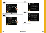
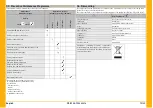
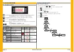
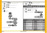
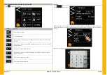
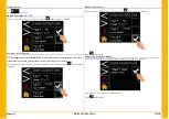
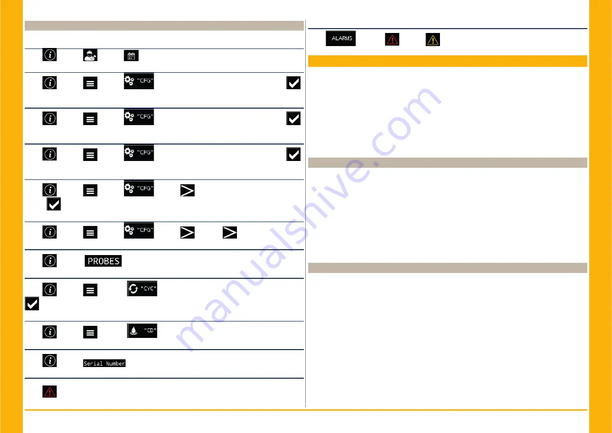
6.3 Rapid menu
Reach the menu in short steps:
Change Data/time
Touch
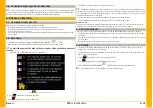
g
g
→ Touch
→ Touch
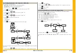
Change of measurement unit from °C to °F
Touch
→ Touch
→ Touch
→ Touch the box on the right and insert the fl ag
to change and confi rm.
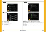
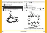
Change Local/rOFF
Touch
→ Touch
→ Touch
→ Touch the box on the right and insert the fl ag
to change and confi rm.
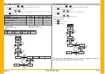
Alarm/waring
Touch
→ Touch
→ Touch
→ Touch the box on the right and insert the fl ag
to change and confi rm.
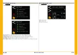
Default parameters
Touch
→ Touch
→ Touch
→ Touch
→ Touch the box on the right and insert
the fl ag
to change and confi rm.
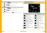
Modbus
Touch
→ Touch
→ Touch
→ Touch
→ Touch
View the probes
Touch
→ Touch
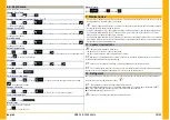
Switch to cycling mode
Touch
→ Touch
→ Touch
→ Touch the box on the right and insert the fl ag
to change and confi rm.
Change the drain
Touch
→ Touch
→ Touch
→ Touch “0/1/2” to make the change.
View serial number
Touch
→ Touch
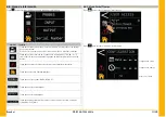
Alarm reset
Restore the nominal conditions.
Touch
→ Touch “Reset
”.
Alarm history
Touch
→ Touch
→ Touch
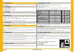
7 Maintenance
• The machine is designed and built to guarantee continuous operation; however, the life of its compo-
nents depends on the maintenance performed.
•
Z
When requesting assistance or spare parts, identify the machine (model and serial number)
by reading the data plate located on the unit.
• Circuits containing 5t < xx < 50t of CO2 should be checked annually to identify any potential leaks.
Per European Regulation EU No. 517/2014 art. 4.3.a, 4.3.b) - Circuits containing 50t < xx < 50t of
CO2 should be checked for leaks every 6 months.
• Per European Regulation EU No. 517/2014 art. 6 - Machines containing 5t CO2 or more, the operator
must keep a written record of the quantity and type of refrigerant used, added or recovered during
maintenance/repair and fi nal disposal.
7.1 General instructions
!
Before any maintenance, make sure:
• the pneumatic circuit is no longer pressurized;
• the dryer is disconnected from the main power supply.
Y
Always use the Manufacturer’s original spare parts: otherwise the Manufacturer is relieved of
all liability regarding machine malfunctioning.
Y
In the event of refrigerant leakage, contact qualifi ed and authorized personnel.
Y
The Schrader valve must only be used in case of machine malfunction: otherwise any damage
caused by incorrect refrigerant charging will not be covered by the warranty.
7.2 Refrigerant
Charging: any damage caused by incorrect refrigerant replacement carried out by unauthorized per-
sonnel will not be covered by the warranty.
Z
Y
The equipment contains fl uorinated greenhouse gases.
At normal temperature and pressure, the R513A refrigerant is a colorless gas classifi ed in SAFETY
GROUP A1 - EN378 (group 2 fl uid according to Directive PED 2014/68/EU)
GWP (Global Warming Potential) = 573.
!
In the event of refrigerant leakage, ventilate the room.
Summary of Contents for PSE 325
Page 2: ......
Page 76: ...14 PSE 325 1000 60Hz 9 7 REFRIGERANT CIRCUIT PSE325 500 Ac PSE325 500 ...
Page 77: ...15 PSE 325 1000 60Hz REFRIGERANT CIRCUIT PSE700 1000 Ac PSE700 PSE800 PSE1000 ...
Page 78: ...16 PSE 325 1000 60Hz REFRIGERANT CIRCUIT PSE700 1000 Wc PSE700 PSE800 PSE1000 ...
Page 87: ...25 PSE 325 1000 60Hz WIRING DIAGRAM PSE700 1000 Sheet 1 of 10 ...
Page 89: ...27 PSE 325 1000 60Hz WIRING DIAGRAM PSE700 1000 Sheet 3 of 10 700 800 1000 ...
Page 90: ...28 PSE 325 1000 60Hz WIRING DIAGRAM PSE700 1000 Sheet 4 of 10 ...
Page 91: ...29 PSE 325 1000 60Hz WIRING DIAGRAM PSE700 1000 Sheet 5 of 10 ...
Page 92: ...30 PSE 325 1000 60Hz WIRING DIAGRAM PSE700 1000 Sheet 6 of 10 ...
Page 93: ...31 PSE 325 1000 60Hz WIRING DIAGRAM PSE700 1000 Sheet 7 of 10 ...
Page 94: ...32 PSE 325 1000 60Hz WIRING DIAGRAM PSE700 1000 Sheet 8 of 10 ...
Page 95: ...33 PSE 325 1000 60Hz WIRING DIAGRAM PSE700 1000 Sheet 9 of 10 ...
Page 96: ...34 PSE 325 1000 60Hz WIRING DIAGRAM PSE700 1000 Sheet 10 of 10 700 1000 ...
Page 97: ......
Page 98: ......
Page 99: ......


