background image

34

35

HEDGE TRIMMER GEARBOX LUBRICATION

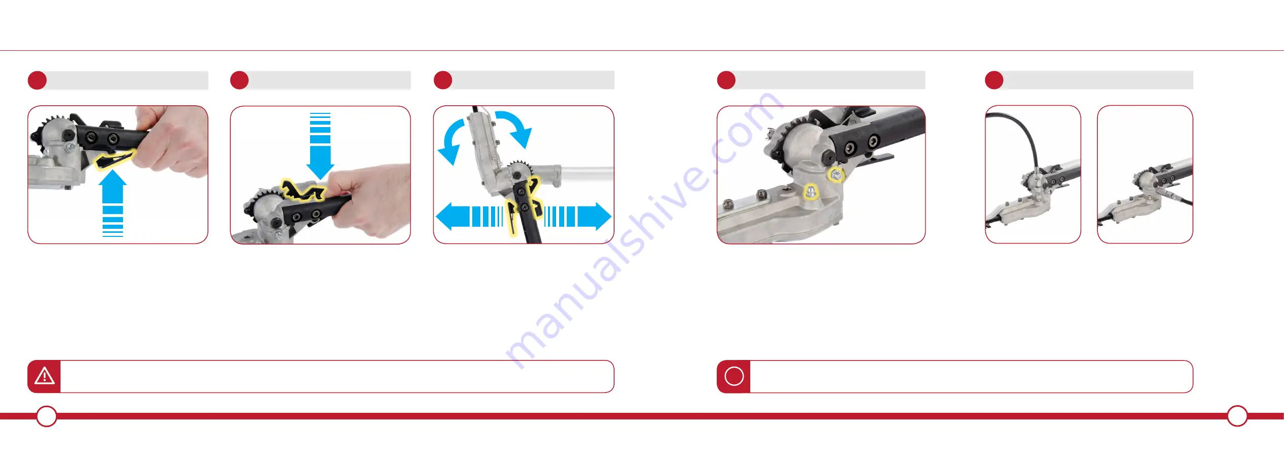
ADJUSTING HEDGE TRIMMER ANGLE

With the engine stopped, grip the 

adjustment handle

Lift the angle adjustment locking lever with 

your index finger and hold

1

LOCKING LEVER

1

2

ANGLE ADJUSTMENT LEVER

Whilst still holding the angle adjustment 

locking lever, press down with your thumb 

on the angle adjustment lever and adjust 

the cutting head to a suitable angle.

WARNING!

 The Hedge Trimmer adjustment handle contains moving parts which could cause injury if used incorrectly.

NOTE:

 Always wear safety gloves when operating moving parts to help prevent the risk of injury.

Once the cutting head is adjusted to the

required angle, release the levers to lock 

the cutting head into position.

2

ADJUSTMENT & LOCK

The components within the Hedge Trimmer 

gearbox have to work very hard and as a result 

MUST remain well lubricated at all times. Before or 

after each use.

There are two grease nipples on the Hedge 

Trimmer gearbox housing. Be sure to add grease 

to both.

Connect a compatible grease gun to the gearbox

assembly's grease nipples. 

Pump gearbox grease into the grease nipples.

Use a general purpose gearbox grease.

1

HEDGE TRIMMER GREASE NIPPLES

2

ADD GREASE TO HEDGE TRIMMER

WARNING!

 Use an appropriate gearbox grease. Failure to do so can result in unit failure.

NOTE:

 Always keep gearbox lubricated either before or after use. Lack of lubrication can cause unit failure

i

Summary of Contents for PGMT-5200

Page 1: ...CLICK TO CHANGE TEXT 1 MULTI TOOL EN OWNERS MANUAL PGMT 5200 ...

Page 2: ...ntained in this manual was accurate at the time of production however Parker Products Ltd may make modifications to the product without notification GENERAL SAFETY 4 5 CHAINSAW GEARBOX LUBRICATION 39 SAFETY SYMBOLS 6 9 CHAIN OIL 40 41 FOR SAFE OPERATION 10 13 INSTALLING THE POLE EXTENSION 42 43 WHATS IN THE BOX 14 15 THE HARNESS 44 46 PRODUCT FEATURES 16 19 STARTING THE ENGINE 48 51 BEFORE USING T...

Page 3: ...rea and a secure footing ALWAYS use the harness supplied while operating the machine NEVER smoke while operating the unit or refilling its fuel tank ALWAYS keep the handles dry clean and free of oil and fuel mixture ALWAYS shut off the engine before putting the product down MAKE SURE all fuel is removed before transportation ALL MAINTENANCE other than that listed in this manual should be carried o...

Page 4: ...r for others To limit the risk of injury fire or electrocution always apply the recommendations indicated DANGER Keep away from sources of ignition Fuel 2 stroke oil mixture ratio WARNING Never operate this power tool within 50ft 15M of wires or power cables 15m 50ft Keep all children bystanders helpers 15 metres away from the machine BEWARE OF THROWN OBJECTS WARNING Danger of kickback BEWARE OF S...

Page 5: ...ULD NOT BE DISPOSED OF WITH HOUSEHOLD WASTE PLEASE RECYCLE WHERE FACILITIES EXIST CHECK YOUR LOCAL AUTHORITY OR RETAILER FOR RECYCLING ADVICE GUARANTEED SOUND POWER LEVEL HOT SURFACES WILL BURN FINGERS OR PALMS REMOVE SPARK PLUG LEAD BEFORE MAINTENANCE WARNING Do not use the Multi Tool in an enclosed space Exhaust fumes contain dangerous carbon monoxide WARNING Spinning cutting line Maximum speed ...

Page 6: ... and swelling of your fingers or any other part of your body see a doctor before getting worse To avoid noise complaints operate product between 9am and 5pm BEFORE STARTING THE ENGINE The area within a perimeter of 15m of the person using the product should be considered a hazardous area into which no one should enter If necessary yellow warning rope and warning signs should be placed around the p...

Page 7: ...enance or checking procedures In the event that any part must be replaced or any maintenance or repair work not described in this manual must be performed please contact Parker Brand Under no circumstances should you ever take apart the product or alter it in any way Doing so might result in the product becoming damaged during operation or the product becoming unable to operate properly HANDLING F...

Page 8: ... HEDGE TRIMMER ATTACHMENT CHAINSAW ATTACHMENT EXTENSION POLE LOWER GUARD WASHER A WASHER B 3 TOOTH BLADE NUT SPLIT PIN LOCKING WASHER Washers nut and split pin are pre installed on the lower shaft i SAFETY GLASSES BAR COVER FUEL MIX BOTTLE SAFETY GLOVES TOOL KIT SPOOL LINE SPARK PLUG WRENCH 2x ALLEN KEYS SPANNER 2xWASHERS 4x ALLEN BOLTS 2x LOCKING KNOBS INTERNATIONAL LANGUAGE USER MANUAL HEDGE TRI...

Page 9: ...16 17 PRODUCT FEATURES PRODUCT FEATURES ENGINE COIL PLUG RECOIL EXHAUST FUEL CAP CHOKE HARNESS POINT SPLIT SHAFT CONNECTOR JOINT LOOP HANDLE THROTTLE TRIGGER ON OFF SWITCH ...

Page 10: ...ADJUSTMENT LEVER CHAIN OIL CAP TENSION SCREW SPROCKET COVER ADJUSTMENT MECHANISM HANDLE PRODUCT FEATURES PRODUCT FEATURES CHAIN OIL FLOW SCREW GREASE NIPPLES BAR ADJUSTMENT LOCKING LEVER BLADES GREASE NIPPLES ...

Page 11: ...th 2 stroke oil at a 40 1 ratio Gasoline Oil WARNING Do not start without adding a 40 1 ratio Gasoline Oil first failure to do so will damage the engine The locking washers may come pre installed on the hub of the machine The hub in needs assembling in different configurations to fit the appropriate attachments Washer A needs to be installed at all times regardless of which attachment is fitted to...

Page 12: ...sition the handle on the shaft connected to the engine in the most comfortable position for the user Attach the guard to the lower shaft using the screws and tools provided 1 ATTACH THE LOWER GUARD NOTE Over tightening the bolts screws can cause damage to the bolt screw and or the machine 3 4 ATTACH THE LOWER GUARD Locate the guard on to the lower shaft using the 4x screws provided Be sure not to ...

Page 13: ...nected correctly the machine will not function in the manner intended ASSEMBLY 5 SHAFT TO JOINT ASSEMBLY 6 ALIGN THE SPLINES 7 8 JOIN THE SHAFTS RELEASE LOCATING PIN 9 TIGHTEN KNOB Release the pin and rotate the lower shaft until the joint is locked into position Secure the joint by tightening the knob To tighten the knob turn in a clockwise direction When inserting the shaft into the joint pay pa...

Page 14: ...s is done by inserting the allen key through the holes highlighted above Lock the axle by placing the allen key inside the locating hole of the collar through washer A and into the axle You can now wind the spool or 3 tooth blade nut onto the thread by turning it anti clockwise Please ensure that the spool is secure and closed correctly and the 3 tooth blade is located centrally on the hub prior t...

Page 15: ... key inside the locating hole of the collar and tighten the locking nut using the wrench provided turning anti clockwise until secured tightly Follow steps 8 9 within Assembly on how to lock the axle IMPORTANT Place the split pin where applicable inside the thread to prevent the nut coming loose 4 SECURE UPPER WASHER TIGHTEN LOCKING NUT 5 SECURE THE NUT NOTE The hub is reverse threaded so to tight...

Page 16: ...le by placing the allen key inside the locating hole of the collar and wind the spool onto the thread by turning anti clockwise Please ensure that the spool is secure and closed correctly prior to use Follow steps 8 9 within Assembly on how to lock the axle To remove the spool follow the above directions in reverse i INSTALLING THE SPOOL Please be aware that Washer A Washer B and 3 Tooth Blade Nut...

Page 17: ...ION It is vital to use the correct shaft for the cutting heads for the machine to function correctly i Locate the Chainsaw attachment pole which can be identified by the identification sticker Remove the red shaft protector from the bottom of the Chainsaw Attachment pole Insert the pole into the attachment The short allen bolt should locate through the attachment housing and into the locator hole ...

Page 18: ...injury Once the cutting head is adjusted to the required angle release the levers to lock the cutting head into position 2 ADJUSTMENT LOCK The components within the Hedge Trimmer gearbox have to work very hard and as a result MUST remain well lubricated at all times Before or after each use There are two grease nipples on the Hedge Trimmer gearbox housing Be sure to add grease to both Connect a co...

Page 19: ...stment of the tensioner may be required to ensure the bar fits correctly over the stud The chain links on the top of the bar must have the arrow pointing away from the housing Loosely lay the saw chain into the groove on the bar start at the nose of the bar Make sure the sprocket teeth sit correctly between the chain links 1 REMOVE SPROCKET COVER 2 ADJUST TENSION SCREW 4 FIT CHAIN GUIDE BAR 3 LOOS...

Page 20: ...ce Sharpen or replace it with an identical one Once satisfied with the chain tension tighten the 10mm nut securely using the spanner provided within the tool kit 1 ADJUST CHAIN TENSION 6 7 CHECK CHAIN TENSION 8 SECURE SPROCKET COVER The components within the gearbox have to work very hard and as a result MUST remain well lubricated at all times Before or after each use Connect a compatible grease ...

Page 21: ...il flow adjustment screw anti clockwise to increase or clockwise to decrease Start the engine and test the flow When a sufficient amount is being thrown from the tip the adjustment is complete A reservoir full of chain oil will run dry long before the engine runs out of fuel Continually check the oil level during use refilling the reservoir before it is empty Fill the reservoir with chain oil Use ...

Page 22: ...ty can arc Electrical current can also be carried through branches especially if they are wet WARNING Maintain a distance of at least 50 feet 15M between the chain saw including any branches it is contacting and any electrical line carrying live current Secure the joint by tightening the knob To tighten the knob turn in a clockwise direction The extension pole is only designed to be used with the ...

Page 23: ...uit your frame Please be aware you may need to re adjust to ensure the harness is in the most comfortable position to suit you Ensure the thigh pad is located in the correct position so it protects you fully from pres sure points created from contact with the machine during use The thigh pad is normally positioned on the right hand side this is the same side that the machine will be positioned You...

Page 24: ...rds Please make sure the machine is properly secured or supported before releasing the quick release hook to prevent damage After use of the quick release hook it will need to be re assembled Place the lower hook over the upper hook with orange tab attached Place the release pin through the slot in the upper hook making sure that the pin passes over the lower hook The quick release hook is now re ...

Page 25: ...re and tight for the carburettor to prime STARTING THE ENGINE 3 CLOSE CHOKE COLD START 3 OPEN CHOKE WARM START For cold engine starts close the choke by sliding the lever upwards For warm engine starts open the choke by sliding the lever downwards A B CHOKE CLOSED CHOKE OPEN WARNING The product is equipped with centrifugal clutch mechanism so the cutting attachment begins to rotate as soon as the ...

Page 26: ...e engine failed to start after several attempts open the choke and repeat pulling the rope or remove the spark plug and dry it STARTING THE ENGINE 6 START THE ENGINE COLD START 6 START THE ENGINE WARM START B A Make sure that the choke is CLOSED 1 Pull the recoil starter twice in quick succession 2 Proceed to Step 6B and follow instructions for warm start 1 Make sure that the choke is OPEN 2 Pull ...

Page 27: ...allows the engine to cool down and return to optimum operating temperature Turn the engine off by placing the on off switch to position O or STOP as illustrated above When restarting the engine after immediately stopping it leave the choke open to prevent flooding the engine THIS PAGE HAS INTENTIONALLY BEEN LEFT BLANK 53 OFF ON ...

Page 28: ...OL LINE OPEN REPLACE SPOOL LINE SPOOL COVER SPOOL CARTRIDGE SPOOL LINE SPOOL SPRING SPOOL BODY BUMP TO FEED LINE LINE FEED DIRECTION LINE FEED DIRECTION PUSH TO UNCLIP WEAR EYE PROTECTION TURN ANTI CLOCKWISE TO ATTACH TO HUB ...

Page 29: ...windings which need to be wound in the direction shown on the body Secure the replacement wire to the cartridge as shown NOTE Replacement strimmer wire should be 2 4mm in diameter i 57 OPEN REPLACE SPOOL LINE 3 SECURE WINDING 4 REPEAT STEP 2 3 Secure the winding inside one of the two lugs to grip the cord and prevent it unwinding Repeat steps 2 3 for the second winding and thread back through the ...

Page 30: ...t the throttle cable loosen or tighten the nuts illustrated above Always allow 1 2mm of play to ensure the cable is not under load at all times When the engine tends to stop frequently at idling mode turn the idle speed adjuster clockwise When the cutting head keeps rotating after releasing the trigger turn the idle speed adjuster counter clockwise THIS PAGE HAS INTENTIONALLY BEEN LEFT BLANK ...

Page 31: ... the engine speed and cutting depth according to the type of material being cut If grass or other object get caught in the blade or if the unit starts to shake or vibrate turn off the engine and check the whole unit Change the blade if it has been damaged Turn off the engine and make sure the blade has completely stopped before checking the blade and removing any object that has got caught in WARN...

Page 32: ... this from happening Position the cutting head near the tree limb making sure it is not touching any other branches CONTROLLING BLADE THRUST Blade thrust can cause serious personal injury It is important that you understand what causes blade thrust and how you can reduce the chance of it and also how you can remain in control of the unit if blade thrust occurs What causes blade thrust Blade thrust...

Page 33: ...he machine remains trapped in a partial cut stop the engine Support the weight of the machine while trying to lift or pull down depending on the side of the chain trapped the branch to release the chain HEDGE TRIMMER WORKING TECHNIQUES Some local authorities impose seasonal bans on hedge cutting Check with your local authority to make sure this does not affect you Beware of hidden objects Check th...

Page 34: ...e cutting head straight Make level arcs so as to encourage the trimmings on to the floor Do not attempt to cut a hedge higher than chest height without using a safe platform WARNING If working on a platform do not attempt to stretch or over reach When cutting with the blade set straight tilt the cutting side of the blades toward the hedge by approximately 0 10 degrees Hedge Trimmer Blade Maintenan...

Page 35: ...when new Contact Parker Brand Engine starts but will not accelerate Carburettor requires adjustment Contact Parker Brand Engine starts but will cut out when the throttle is pressed Choke is in start closed position When the engine is running the choke should remain open the downwards position TROUBLESHOOTING ENGINE PROBLEM POSSIBLE CAUSE SOLUTION Engine starts but will only run at high speed at ha...

Page 36: ...m shafts are not correctly engaged Remove the bottom shaft and re insert ensuring the joint is correctly connected and engaged Three tooth blade is not installed centrally Reinstall the three tooth blade ensuring the blade is installed centrally and with the correct washers TROUBLESHOOTING SPOOL 3 TOOTH BLADE PROBLEM POSSIBLE CAUSE SOLUTION Spool will not unwind String welded to itself Lubricate w...

Page 37: ...ed Chain moves while engine is at idle Idle is set too high Adjust the idle setting until the chain stops PROBLEM POSSIBLE CAUSE SOLUTION Poor cutting performance Clogged blades Blades blunt Stop engine Clean and lubricate blade assembly Have the blades serviced or replaced by an authorised service centre Unusual noise from the cutting head Insufficient grease in the gearbox assembly Stop engine A...

Page 38: ...n fuel tank Check X Replace X X X Gearbox Lubrication Check X X X Replenish X Before starting work After finishing work or daily After each refuelling stop Weekly Monthly Yearly If problem If damaged As required ENGINE Carburettor Check idle adjustment the cutting attachment must not rotate X X Adjust idle speed X Spark Plug Readjust electrode gap X Replace after every 100 operating hours Cooling ...

Page 39: ...bration Elements Check X X X Engine 10mm Model 1E44F 5 Displacement 52 0cm3 Fuel Mixture Gasoline 40 Oil 1 Carburettor Diaphragm type Ignition System Transistor Controlled Flywheel Magneto Spark Plug LD BM6A Fuel Tank Capacity cm 1 2 Litres Starter Recoil Clutch Centrifugal Cutting Head Rotating Direction Counter Clockwise Operator View 3 Tooth Blade Size 1 4 x 255 x 254 Spool Wire Size 2 4mm Chai...

Page 40: ...oducts Ltd Being the responsible person appointed by the manufacturer Signed Date 19 03 19 Name Jason Parker Position Managing Director Parker Products Ltd Guarantees the product against defective material or damage for period of 12 months from the date of purchase A proof of purchase must be provided with the product In case of any fault please return the product to Parker Products Ltd or an auth...

Page 41: ...WWW PARKERBRAND CO UK PGMT 5200 Rev 1 1 April 2019 ...

Reviews: