Parker Hannifin Corporation
Pneumatic Division Europe
www.parker.com/pde
31
0V-
13
12
A1
A2
18
19
20
21
15
14
16
17
2
9
10
11
5
6
7
8
0
1
3
4
+24V
SOL 1
SW 1
S1
RESET
SW 2
A4 BLACK
A2 WHITE
A3 BLUE
B4 BLACK
B2 WHITE
B3 BLUE
B1 BROWN
B5 GREY
SOL 2
Integration Guide
Rockwell 440C-CR30
FRL-SIF-120
_EU
Parker Pneumatic
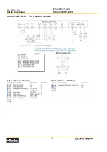
Rockwell Wiring Schematic (without sensor test pulse) to Interface to
Safety Exhaust Valve
This schematic shows an example of
an e-stop circuit for reference only.
M12 Pinouts for P33
With this schematic it is possible to achieve up to category 4 PL e if properly implemented.
External monitoring program for Rockwell 440C-CR30
a) If I.5 = I.6 = I.0 = I.1 = 1 AND no faults present THEN SET O.18 = O.19 = 1 when commanded
b) Sensor discrepancy error: I.7 <> I.8 (max. discrepancy time = 150 msec)
c) Loss of pressure error: O.18 = O.19 = 1 AND I.7 = I.8 = 0
followed by I.5 = 1 OR I.6 =1 AND O.18 = O.19 = 1
d) System pressure error: O.18 = O.19 = 1 AND I.7 = I.8 = 1 for x amount of time (x is system pressurization time
dependent on volume) Default 3 secs.
e) IF sensor discrepancy error OR loss of pressure error OR system pressure error THEN reset O.18 = O.19 = 0
Errors must be reset only after maintenance acknowledgement
* Programs provided in this integration guide are for reference only. These programs have not been certified or tested
unless stated otherwise.
A
5
1
3
4
2
Sol 2
Sol 1
+
-
+
1 Brown
2 White
3 Blue
4 Black
5 Grey
5
1
3
4
2
SW
1
SW
2
B
+
+
-


