17
Bulletin HY22-3220A/US
Instruction Manual
550 Series Hydraulic Power Units
Troubleshooting
operating well because of worn orifices or seals.
Always remove and check the hot components first.
Check Oil Samples Periodically
Periodically checking oil temperature and siphoning an oil
sample from the reservoir, comparing it with a sample of new,
clean oil, is good preventive maintenance.
Oil that has been running too hot will look darker and feel
thinner than new oil. It will also smell burned. Normally it
will contain more contaminants, because hot oil leads to
accelerated wear of component parts.
Recommended Spare Parts
The only recommended maintenance component is the suction
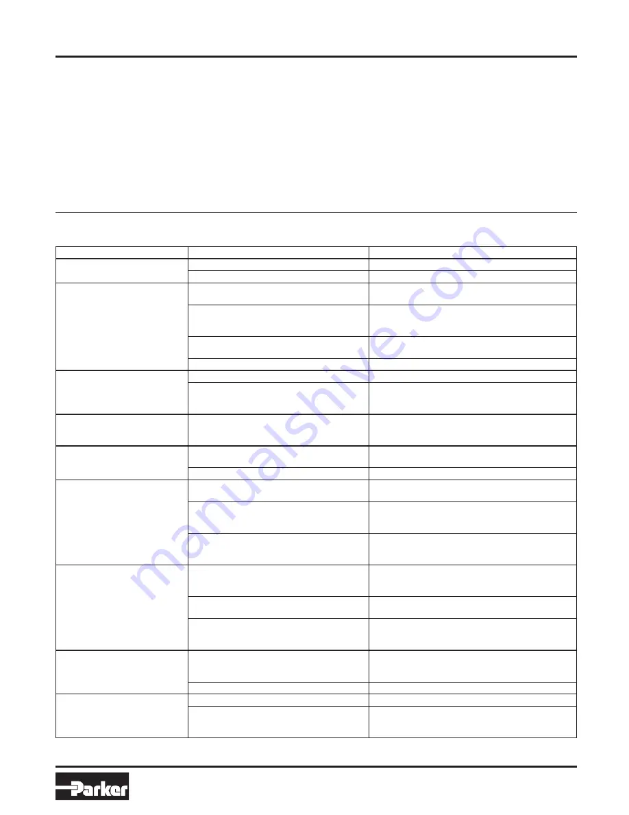
FAILURE MODE
CAUSE(S)
CORRECTIVE ACTION
Motor will not run
No power to the motor
Ensure proper voltage is available at motor
Motor is wired incorrectly
Wire the motor per the Installation instructions
Motor runs, but no flow
Reservoir does not have enough fluid
Fill the reservoir per the Installation instructions with an
approved fluid
Motor rotation is not clockwise from fan end
Single phase motors: wire per the Installation instructions
Three phase: interchange any two of the three power
leads
Two position/two way valve is not closed
If a normally open valve, energize to close. If a normally
closed valve, de-energize coil
D03/NG6 valve is not shifted from center position Energize one of the valve solenoids
Low flow
Incorrect pump was selected or installed
Contact your distributor for rework instructions
Relief valve is set too low for application allowing
bypass
Increase the relief valve setting ensuring the flow and
pressure output are still within the electric motor’s
capability
Reservoir overflows on cylinder
retract
Reservoir is too full. Filling the reservoir with
the actuators extended will cause an overflow
condition when actuators are retracted
Ensure that, with the system full of oil and the actuators
fully retracted, the reservoir is at the full condition
Motor gets hot/high current
draw
Motor is not wired per the Installation instructions Ensure proper voltage is available at motor
Wire the motor per the Installation instructions
Will not build pressure
Reservoir does not have enough fluid
Fill the reservoir per the Installation instructions with an
approved fluid
Motor rotation is not clockwise from fan end
Single phase motors: wire per the Installation instructions
Three phase: interchange any two of the three power
leads
Relief valve is set too low for application allowing
bypass
Increase the relief valve setting ensuring the flow and
pressure output are still within the electric motor’s
capability
Will not hold pressure
Circuit type selected will not hold pressure
Ensure the model code calls out the D1 circuit, the SW
circuit or an S_ or P_ circuit. Only these circuits are
designed to hold pressure
Two position/two way valve is not closed
If a normally open valve, energize to close. If a normally
closed valve, de-energize coil
D03/NG6 valve selected without the Manapak
check valve block
D03/NG6 directional valves are not designed to hold
pressure. Contact your Parker Oildyne distributor to
purchase a Manapak check valve manifold
Leaks at fittings
Hose ends/fitting adapters are not the correct
type for the 550 Series ports
For the D0 and D1 circuits, the power unit includes JIC-6
male extension fittings. For all other circuits, the power
unit has SAE-6 male ports
Fittings are not tightened properly
Ensure all fittings are properly tightened
Actuator will not move both ways
Valve coils are not energized properly
Ensure the directional valve coils are operating properly
Relief valve is set too low for application allowing
bypass
Increase the relief valve setting ensuring the flow and
pressure output are still within the electric motor’s
capability
strainer, Oildyne part number 410542. See the Maintenance
section on page 14 for instructions on replacing the suction
strainer.
Be aware of risk of hazards if poor quality replacement parts are
used or are obtained from an unauthorized source. Using non-
Parker supplied components will void the warranty.
Conclusive Unit Failure
If the operation of the unit cannot be restored after attempts at
the troubleshooting suggestions listed below, please contact
your local Parker distributor or the Oildyne Division directly to
arrange for warranty replacement/repair if within the warranty
period.
Troubleshooting
Parker Hannifin
HPS Division
New Hope, MN 55428 USA