Parker Pro Display 12 Instruction Book
10/54
Header Link to Contents
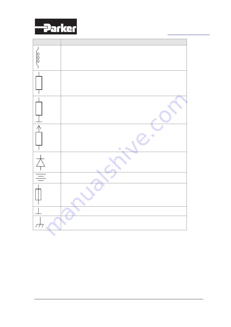
Symbol
Meaning
Load
Resistor
Pull-down resistor
Pull-up resistor
Diode
Battery
Fuse
Ground
Chassis ground
Page 1: ...Instruction Book PARKER PRO DISPLAY 12 Publ No MSG17 4022 IB UK Edition 12 2019...
Page 2: ...ATH PERSONAL INJURY AND PROPERTY DAMAGE This document and other information from Parker Hannifin Corporation its subsidiaries and authorised distributors provide product and or system options for furt...
Page 3: ...Product Description 11 4 1 General 11 4 2 System overview 14 4 3 Infotainment 16 4 3 1 Audio line I O 16 4 3 2 Audio line output 16 4 3 3 Microphone input 17 4 3 4 FM radio tuner 18 4 3 5 Wireless com...
Page 4: ...g 33 7 1 Mounting the module 33 7 1 1 Assembly surface conciderations 33 7 2 Dashboard or panel assembly 33 7 2 1 Panel assembly 33 7 3 Ball swivel mount 34 8 Installation 37 8 1 Electrical connection...
Page 5: ...der Link to Contents The following table provides an overview of the changes made to this document over the course of its publication history Table 1 Publication history Release Date Description of Ch...
Page 6: ...When you see these symbols follow the instructions carefully and proceed with caution Note character style Note style for regular manual text 1 2 Overview of relevant documentation The following publi...
Page 7: ...ation with strong electromagnetic interference fields can in extreme cases cause an unintentional change in the speed of the output function 2 3 Welding after installation Complete as much as possible...
Page 8: ...rical functions have been verified Do not start the machine if anyone is near the machine Ensure that no one is in front of behind or nearby the machine when first starting up the machine Follow the i...
Page 9: ...be found throughout this manual The following table provides meanings for the different symbols used in those diagrams Symbol Meaning General input General output Frequency input Analogue input Frequ...
Page 10: ...Parker Pro Display 12 Instruction Book 10 54 Header Link to Contents Symbol Meaning Load Resistor Pull down resistor Pull up resistor Diode Battery Fuse Ground Chassis ground...
Page 11: ...arker UX Platform UXP applications created with Parker Application Designer software development environment Figure 1 Pro Display 12 Table 3 Pro Display 12 product part numbers Item P N Description 88...
Page 12: ...tection Audio Stereo Line IN Line OUT Audio input sources 5 pcs selectable from following a Bluetooth audio b Audio line input selectable with FM radio c FM radio selectable with audio line input d Mi...
Page 13: ...ass features Thickness 1 8 mm Glass type Strenghtened clear Printing Edge printing Black Touchscreen display mechanical interface Optical bonding between cover glass and LCD display glass for improved...
Page 14: ...BIAS FM RADIO MIC IN AUDIO LINE IN WIRELESS INTERFACES BLUETOOTH WIFI BT HANDSFREE 12 1 TFT DISPLAY TOUCHSCREEN HS OUT AUDIO LINE OUT CAMERA INPUTS VIDEO IN 1 VIDEO IN 2 VIDEO IN 3 VIDEO IN 4 CoCPU T...
Page 15: ...en and a high performance TFT LCD display panel All I O are protected against short circuit to GND and VBatt as well as against reverse polarity Pro Display is intended for systems using either nomina...
Page 16: ...module When Audio Line I O is configured to Audio Line OUT mode its working like normal Line Output In Line IN mode this I O is normal Line Input Table 5 Audio Line IO specifications Line IN mode See...
Page 17: ...two channels It is possible to also utilise single channel if this would be adequate for the end application 4 3 3 Microphone input Microphone input is provided Microphone input can be used for both g...
Page 18: ...tings This example application can be used for scanning available access points and to make connections with desired access points 4 3 5 2 Bluetooth Pro Display includes wireless Bluetooth function to...
Page 19: ...VIDEO SIGNAL Video GND VIDEO SIGNAL Video GND CVBS_IN 3 CVBS_IN 4 12V GND 12V GND 12V GND 12V GND 12V Ext Camera supply VIDEO INPUTS VIDEO IN 1 VIDEO IN 2 PRO DISPLAY 12 C5 4 C5 1 C5 5 VIDEO IN 3 VID...
Page 20: ...odule cannot be powered through ignition This multi level digital ignition signal has following functional states Table 10 Ignition signal functionality State Functionality OFF Inactive the main power...
Page 21: ...mode functionality Wake up can be used for two functions Entering silent start up and waking up from sleep mode In operation mode this input can be used as digital input PRO DISPLAY WAKE UP IN SWITCH...
Page 22: ...re and therefore it is not enabled during boot up This shall be taken into account in end application design If Pro Display SW controlled CAN termination is not feasible for end application then exter...
Page 23: ...count in the end application environment 4 6 3 RS232 One RS232 port is provided and available on main connector C2 The port consists of TX RX and GND signals There is no handshaking Baud rate is confi...
Page 24: ...es Multi finger support 4 7 2 Display Pro Display 12 uses a high performance sunlight readable 12 1 IPS colour TFT LCD with white LED backlight The 12 1 display is widescreen and has a resolution of 1...
Page 25: ...sensing purposes by the application 4 8 2 Supply supervision voltage measurement Pro Display has internal monitoring for a module s internal power supplies This is implemented with a dedicated microco...
Page 26: ...this plug is placed back and tightened after user actions so that water dust ingress into device is prevented NOTICE Application developer can configure LED functionality according the development nee...
Page 27: ...ss SD video recording 4MB s 32Mbps 4 Full HD video recording 6MB s 48Mbps 6 Full HD video recording HD still consecutive shooting 10MB s 80Mbps 10 For higher potential of recording real time broadcast...
Page 28: ...ation of system functionality into separate apps The apps will have a standard interface to UXP which will enable them to have their own life cycle as well as an interface to exchange data with the ma...
Page 29: ...installed Development unit Pro Display 12 serial production unit can be converted into a development unit by a software update The development unit software licence can be requested separately from P...
Page 30: ...mode Run mode is started after Vbatt is in proper voltage level and ignition signal is ON Entering into sleep mode from run mode is handled from application software Return from sleep mode is triggere...
Page 31: ...overvoltage event Power up sequence Supplies OK Figure 15 Pro Display operating modes 5 5 1 Sleep mode Sleep mode is a standby mode for the unit Only certain module functions are in use during sleep m...
Page 32: ...onstruction The Pro Display unit mechanics consist of a die cast aluminium back cover PC ABS front frame and physically strengthened cover glass with anti glare coating Figure 16 Pro Display 12 front...
Page 33: ...gasket between device flange and panel cut out edges to ensure adequate sealing for the installation location and prevent device to vibrate in assembly location during operation B Prepare and attach e...
Page 34: ...ended for assemblies where the installer can operate behind the assembly surface for example cabinet doors Cutout dimensioning for Pro Display panel mounting on vehicle Figure 19 Cutout dimensioning f...
Page 35: ...f the Pro Display and fasten it with 4 pcs of M4 screws Apply a torque of about 2 7 Nm B Fix swivel arm loosely to RAM ball just attached into Pro display C Attach the RAM ball into vehicle s assembly...
Page 36: ...ay is mounted into suitable vewing angle in the vehicle J Ensure that Pro Display is locked into its final mounting position by trying to move it gently When there is no noticeable movement detected t...
Page 37: ...r side of the Pro Display unit The following chapters present available connections C3 C4 C1 C5 C6 C2 ANT Figure 21 Pro Display 12 back cover with connectors Figure 22 Pro Display interfaces 8 Install...
Page 38: ...up the device from sleep mode C1 8 CAN4_H CAN Channel 4 High signal C1 9 CAN3_H CAN Channel 3 High signal C1 10 CAN2_H CAN Channel 2 High signal C1 11 CAN1_H CAN Channel 1 High signal C1 12 VBATT Supp...
Page 39: ...le to fail to meet the environmental specification Make Y connections or splices using weatherproof methods external to the Pro Display connectors NOTICE It is recommended to twist following wires in...
Page 40: ...ing connector types are available from several manufacturers See Table 26 C3 C4 and C6 Mating connector type to interface the Pro Display into system in section 8 1 4 as example of mating connector ty...
Page 41: ...e Harting M12 L Male unshielded C5 A Harting 21 03 272 1505 Straight Harting M12 L Male Crimp angled C5 A Harting 21 03 822 3505 Angled Suitable M12 male A coded 5pin connectors are also available fro...
Page 42: ...D coded 4pin connectors are also available from several other manufacturers Ethernet cable is available from Parker see Appendix C for ordering codes 8 1 5 Micro SD card interface Micro SD is possible...
Page 43: ...C D E Figure 26 subfigures A to E Micro SD card installation into connection C1 on the rear side of the Pro Display Current product version includes black cover plug Removal procedure happens in back...
Page 44: ...Crimp Plug connector Amphenol SMA1111A1 3GT50G 1 50 Straight Normal cable Amphenol SMA1111A2 3GT50G 5 50 Straight Miniatyre cable SMA R A Plug connector Amphenol SMA1142C2 3GT50G 1 50 Angled Normal c...
Page 45: ...dule do not connect the emergency stop as a signal input only The emergency stop must be installed so that the risk of module reverse feed is avoided 8 2 3 Connecting of supply voltage The supply volt...
Page 46: ...nit 9 1 Procedures with software Initializing Pro Display serial products 88PROD12AS10 A Insert USB stick with the system ID file and certified application packages B Turn on the Pro Display C The sys...
Page 47: ...Environment ISO15003 and ISO16750 2 EMC ISO13766 and ISO14982 Certification CE E Mark E17 10 R 05 0150 Table 30 Mechanical environmental ratings Feature Rating Value Mechanical climate environment IS...
Page 48: ...gital audio to module record I O Digital Voltage inputs 1 x Ignition keylock input 1 x Wake up input Outputs 1 x High side output Vbatt 1500mA max Internal features 3 axis acceleration sensor Supply s...
Page 49: ...ture 85 C Time 96 h Low temperature storage IEC 60068 2 1 Temperature 40 C Time 96 h Damp heat IEC 60068 2 78 Temperature 40 C Test humidity 93 RH Test time 21 days Damp heat cyclic IEC 60068 2 30 12...
Page 50: ...4 Test Fh ISO 16750 3 Test duration 32 h in each axis Test all mutual perpendicular axis Mechanical shock IEC 60068 2 27 Acceleration 500 m s2 10 shocks in all 3 axes in both directions Bump EN 60068...
Page 51: ...ngress protection IP65 Water Ingress Category 1 IPX5 Salt mist EN 60068 2 52 Test Kb Test time 72 hours Chemical brush exposure ISO 15003 Temperature 25 C Test humidity 50 RH Test time 100 h Chemicals...
Page 52: ...4V 12V system Duration 5 min Slow decrease and increase of supply voltage ISO 16750 2 Supply voltage range 8 to 36V Decrease the supply voltage from Umax to 0V and then increase it from 0V to Umax Cha...
Page 53: ...iated RF emission CISPR 25 ed3 0 III Radiated RF susceptibility ISO 11452 1 ISO 11452 2 IV Immunity to low frequency magnetic fields ISO 11452 8 IV Conducted RF emission CISPR 25 ed3 0 III Conducted s...
Page 54: ...HK Development harness kit for Pro Display for product development and table testing C1 C2 main connector harness equipped with most common communication and audio interface connectors 65RAM1KIT 1 RAM...