background image

8


,

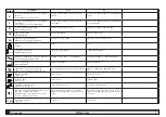
  7.4 Technical data

PCW420-650

MODEL

Amb


H

2

0

% gly

27

(lb)

(Kg)

13

dB[A]

Min

Max

ΔT

(gal)

(l)

PCW420

3307

1500

+32°F/+122°F

0 °C /+ 50°C

41 °F / 113°F

14°F+113°F(---)

5 °C / 45°C

-18°C+45°C(---)

2”½” BSPT-

F

supplied 

with 

adaptors

2”½ NPT-F

1/2”

1/2”

62

32°F

0°C

86°F

30°C

4-27°F

2-15°C

30

87 PSIg

6 bar

264

1000

PCW510

3968

1800

PCW650

4630

2100

64

MODEL

R407C

F.L.A. [A] 460V±10%/3ph/60Hz

(Ø) IP

(lb)

(Kg)

(CO2)

MC1-4

EV1-3

P

HP1

LP1

PV1-2

P3

P5

PCW420

39.7

2x18

63.86

406-304 PSIg

28-21 bar

22-51 PSIg

1.5-3.5 bar

ON: 261 PSIg

OFF: 203 

PSIg

ON: 18 bar

OFF: 14 bar

4 x19.2

2 x 2.5

7.3

10.3

3AWG

54

PCW510

41.3

2x19

67.41

4 x 25.6

1AWG

PCW650

44

2x20

70.96

4 x 27.8

3 x 2.5

Summary of Contents for Hyperchill PCW420

Page 1: ...PCW420 PCW510 PCW650 Hyperchill 60Hz DATE 14 02 2022 Rev 17 CODE 398H272297 EN User Manual ES Manual de uso FR Manuel d utilisation PT Manual do utilizador...

Page 2: ......

Page 3: ...right to modify this manual at any time For the most comprehensive and updated information the user is advised to consult the manual supplied with the unit CAUTION Moving parts hot parts and risk of...

Page 4: ...7 PSIg 6 bar Y Always install mesh filters on the water inlet and outlet pipelines Y If the hydraulic circuit is intercepted by automatic valves protect the pump with an anti hammering system Y If the...

Page 5: ...at the machine and the auxiliary equipment are earthed and protected against short circuit and or overload Once the unit has been connected and the upstream main switch closed thereby connecting the p...

Page 6: ...ure limit values Pmax and Pmin indicated on the pump data plate P1 pressure with pump ON P0 pressure with pump OFF Pmin P1 P0 Pmax Example n 1 Conditions closed circuit pressure P0 29 PSIg 2 bar pump...

Page 7: ...5 U 0 0 4 4 7 B7 sensor parameters PARAMETER CODE TYPE DEFAULT High temperature configuration cHA7 U 0 High temperature alarm HA7 U 60 0 140 0 Low temperature alarm LA7 U 3 0 37 4 Sensor calibration C...

Page 8: ...w pressure alarm 1 from pres sure switch M ID3 tP L7 Pump thermal cutout alarm M ID4 LL L8 Water tank low water level alarm No water flow A ID6 PII L9 Protection alarm compressor 1 Phases monitor M ID...

Page 9: ...imum chiller efficiency and reliability carry out a Z every 6 months clean the condenser fins and make sure compressor electrical absorption is within the dataplate values b Z kit for maintenance par...

Page 10: ...FILTER CLOGGED RENEW THE FILTER CONDENSER FINS DIRTY CLEAN THE FINS OF THE CONDENSER CONDENSER SURFACES CLOGGED CLEAR THE FRONT SURFACE OF THE CON DENSER INSUFFICIENT WATER FLOW INCREASE THE FLOW RATE...

Page 11: ...a el derecho de modi car sin previo aviso la informaci n de este manual Para que la infor maci n resulte completa se recomienda al usuario consultar el manual a pie de m quina PRECAUCI N Partes m vile...

Page 12: ...Se recomienda instalar filtros de red en los tubos de entrada y salida del agua Y Si el circuito hidr ulico posee v lvulas autom ticas de corte proteger la bomba con sistemas contra golpe de ariete Y...

Page 13: ...el equipo cuando se cierra el interruptor ge neral de alimentaci n para energizarlo la tensi n en el circuito el ctrico alcanza valores peligrosos Se recomienda la m xima precauci n 3 4 2 Alarma gene...

Page 14: ...o leer P1 y P0 y los valores l mite de presi n Pm x y Pm n indicados en la placa de datos de la bomba P1 presi n con bomba ON P0 presi n con bomba OFF Pm n P1 P0 Pm x Ejemplo n 1 Condiciones circuito...

Page 15: ...baja temperatura LA5 U 20 0 4 0 Calibraci n de la sonda CA5 U 0 0 4 4 7 Par metros de la sonda B7 PARAMETER CODE TYPE DEFAULT Configuraci n alta temperatura cHA7 U 0 Alarma de alta temperatura HA7 U 6...

Page 16: ...larma alta presi n 1 desde presostato M ID2 LPI L6 Alarma baja presi n 1 desde presostato M ID3 tP L7 Alarma t rmico de la bomba M ID4 LL L8 Alarma bajo nivel de agua en el dep sito Falta flujo de agu...

Page 17: ...cia y fiabilidad del refrigerador hay que a Z ocada 6 meses climpiar las aletas del condensador y contro lar que la absorci n de corriente del compresor est dentro de los valores nominales b Z kit de...

Page 18: ...TASCADO SUSTITUIR EL FILTRO ALETAS DEL CONDENSADOR SUCIAS LIMPIAR LAS ALETAS DEL CONDENSADOR SUPERFICIE DEL CONDENSADOR OBSTRUIDA LIBERAR LA SUPERFICIE FRONTAL DEL CONDENSADOR CAUDAL DE AGUA INSUFICIE...

Page 19: ...parfaitement conformes pour une utilisation correcte de cette m me unit ou de ses composants ATTENTION Le fabricant se r serve le droit de modi er sans aucun pr avis les informations contenues dans c...

Page 20: ...nseill de toujours installer des filtres grillag s sur les tuyauteries d entr e et de sortie de l eau Y Si le circuit hydraulique est intercept par des soupapes auto matiques prot ger la pompe avec de...

Page 21: ...iaires sont bien mis la terre et qu ils sont prot g s contre les courts circuits et ou les surcharges Apr s avoir branch l unit et ferm l interrupteur g n ral en amont mettant ainsi la machine sous te...

Page 22: ...paragraphe 4 5 b V rifier le fonctionnement de la pompe avec le manom tre lire P1 et P0 et les valeurs limites de pression Pmax et Pmin inscrites sur la plaquette signal tique de la pompe P1 pression...

Page 23: ...DE TYPE DEFAULT Alarme haute temp rature HA3 U 60 0 140 0 Alarme basse temp rature LA3 U 20 0 4 0 Calibrage sonde CA3 U 0 0 4 4 6 Param tres sonde B5 PARAMETER CODE TYPE DEFAULT Alarme haute temp ratu...

Page 24: ...S lectionner le param tre b01 ou b02 avec les touches P3 et P4 puis appuyer sur la touche P2 SEL pour afficher la temp rature 4 Appuyer sur la touche P1 PRG pour sortir 4 6 Gestion alarmes 4 6 1 Alarm...

Page 25: ...ience maximum et la fiabilit de l ap pareil proc der comme suit a Z tous les 6 mois nettoyage des ailettes du condenseur et v rifier que l absorption lectrique du compresseur se situe dans les valeurs...

Page 26: ...TES DU CONDENSATEUR SALES NETTOYER LES AILETTES DU CONDENSATEUR SURFACE DU CONDENSEUR BOUCH E LIB RER LA SURFACE FRONTALE DU CONDENSATEUR D BIT D EAU INSUFFISANT AUMENTARE LA PORTATA DEL FLUI DO DA RA...

Page 27: ...serva se o direito de modi car as infor ma es contidas no presente manual sem incorrer na obriga o de avis las previamente Para obter informa es completas e actualizadas recomenda se ao utilizador de...

Page 28: ...e entrada e sa da de gua Y Se o circuito hidr ulico for interceptado por v lvulas autom ticas proteja a bomba com sistemas anti golpe de ariete Y Se o circuito for esvaziado para paragens prolongadas...

Page 29: ...arelhos auxiliares foram ligados terra e protegidos contra curto circuitos e ou sobrecargas Uma vez ligada a unidade e uma vez fechado o interruptor geral situado a montante conferindo assim tens o m...

Page 30: ...o funcionamento correcto da bomba utilizar um ma n metro consultar P1 e P0 e os valores limites de press o Pmax e Pmin indicados na chapa de caracter sticas da bomba P1 press o com bomba ON P0 press...

Page 31: ...U 20 0 4 0 Calibragem da sonda CA3 U 0 0 4 4 6 Par metros da sonda B5 PARAMETER CODE TYPE DEFAULT Alarme de temperatura elevada HA5 U 60 0 140 0 Alarme de baixa temperatura LA5 U 20 0 4 0 Calibragem d...

Page 32: ...2 LPI L6 Alarme de baixa press o 1 do press stato M ID3 tP L7 Alarme t rmico da bomba M ID4 LL L8 Alarme de baixo n vel de gua no reservat rio Aus ncia de fluxo de gua A ID6 PII L9 Alarme de protec o...

Page 33: ...preventiva Para garantir a m xima efici ncia e fiabilidade do refrigerador ao longo do tempo verifique a Z de 6 em 6 meses limpeza do condensador e verifica o da alimenta o el ctrica do compressor den...

Page 34: ...ENTUPIDO SUBSTITUA O FILTRO ALHETAS DO CONDENSADOR SUJAS LIMPE AS ALHETAS DO CONDENSADOR SUPERF CIE DO CONDENSADOR OBSTRU DA DESOBSTRUA A SUPERF CIE FRONTAL DO CONDENSADOR D BITO DE GUA INSUFICIENTE...

Page 35: ......

Page 36: ...fg E mail gsfsupport parker com Parker Hannifin Manufacturing S r l Sede Legale Via Sebastiano Caboto 1 Palazzina A 20094 Corsico MI Italy Sede Operativa Gas Separation and Filtration Division EMEA St...

Page 37: ...Ap ndice Appendix Appendice Anexo DATE 14 02 2022 Rev 17 CODE 398H272297...

Page 38: ......

Page 39: ...mperature Temp rature ambiante Temperatura ambiente Durante el transporte y el almacenamiento During transport and stockage Pendant le transport et l entreposage Durante o transporte e armazenamento T...

Page 40: ...maximum Temperatura m xima IP Grado de protecci n Protection degree Degr de protection Grau de prote o Salida aire de condensaci n Condensation air outlet Sortie air de condensation Sa da do ar de con...

Page 41: ...de l eau V lvula de descarga da gua 15 Man metro del agua Water manometer Manom tre eau Man metro de gua 16 Man metro entrada refrigerante Refrigerant suction manometer Manom tre aspiration r frig ra...

Page 42: ...rifo Cock Robinet Torneira A2 Pantalla local Local display Afficheur local Visor local QS Interruptor seccionador g neral Main disconnector switch Interrupteur sectionneur g n ral Interruptor secciona...

Page 43: ...icas RO ON OFF a distancia Remote ON OFF ON OFF distance ON OFF remoto PI1 4 Protecci n integral compresor Compressor protection Protection int grale compresseur Protec o integral do compressor A100 M...

Page 44: ...or KRA1 Contactor resistencia antihielo Antifreeze heater contactor Contacteur r sistance antigel Contactor da resist ncia anti gelo RA1 Resistencia antihielo Antifreeze heater R sistance antigel Resi...

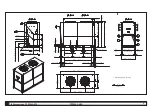
Page 45: ...7 7 2 Handling 7 3 Operating space PCW420 650 7 2 Handling A B C 1600 mm 4000 mm 7000 mm A B C D E D E 970 mm 1000 mm 7 3 Operating space 1500 mm m m 0 0 5 1 m m 0 0 5 1 1500 mm...

Page 46: ...2 62 32 F 0 C 86 F 30 C 4 27 F 2 15 C 30 87 PSIg 6 bar 264 1000 PCW510 3968 1800 PCW650 4630 2100 64 MODEL R407C F L A A 460V 10 3ph 60Hz IP lb Kg CO2 MC1 4 EV1 3 P HP1 LP1 PV1 2 P3 P5 PCW420 39 7 2x1...

Page 47: ...12 62 19 554 5 21 81 19 318 5 12 51 19 2187 86 09 110 4 34 2297 90 43 40 1 57 51 2 01 47 5 1 87 No 8 HOLES 18 1185 46 65 47 5 1 87 95 3 74 1090 42 91 95 3 74 5 2 96 19 227 5 8 94 19 1290 50 79 80 3 15...

Page 48: ...260 128 35 No 8 HOLES 18 1185 46 65 47 5 1 87 47 5 1 87 95 3 74 95 3 74 1090 42 91 1115 43 90 1115 43 90 948 37 32 555 5 21 85 19 3270 128 74 645 25 39 645 25 39 731 5 28 80 731 5 28 80 903 5 35 57 32...

Page 49: ...8H114768 398H114769 398H114754 Biogas 398H473645 398H473646 fan motor Centrifugal 3 398H381608 sigh glass 6 398H348022 refrigerant filter body 7 398H206227 Filter cartridge 398H206053 expansion valve...

Page 50: ...e sensor 6m 29 398H275235 Evaporator temperature sensor 6m 30 398H275235 local display A2 398H275698 main diconnector switch QS 398H256425 compressor automatic switch QF1 4 398H256290 398H256363 compr...

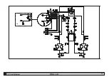
Page 51: ...13 7 5 Circuit diagram PCW420 650 NP PCW650 PCW650 A1...

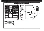
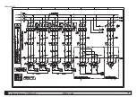
Page 52: ...14 7 6 Wiring diagram PCW420 510 PCW420 650 Sheet 1 of 11...

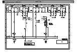
Page 53: ...15 7 6 Wiring diagram PCW420 510 PCW420 650 Sheet 2 of 11...

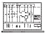
Page 54: ...16 7 6 Wiring diagram PCW420 510 PCW420 650 Sheet 3 of 11...

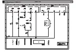
Page 55: ...17 7 6 Wiring diagram PCW420 510 PCW420 650 Sheet 4 of 11...

Page 56: ...18 7 6 Wiring diagram PCW420 510 PCW420 650 Sheet 5 of 11...

Page 57: ...19 7 6 Wiring diagram PCW420 510 PCW420 650 Sheet 6 of 11...

Page 58: ...20 7 6 Wiring diagram PCW420 510 PCW420 650 Sheet 7 of 11...

Page 59: ...21 7 6 Wiring diagram PCW420 510 PCW420 650 Sheet 8 of 11...

Page 60: ...22 7 6 Wiring diagram PCW420 510 PCW420 650 Sheet 9 of 11...

Page 61: ...23 7 6 Wiring diagram PCW420 510 PCW420 650 Sheet 10 of 11...

Page 62: ...24 7 6 Wiring diagram PCW420 510 PCW420 650 Sheet 11 of 11...

Page 63: ...25 7 6 Wiring diagram PCW650 PCW420 650 Sheet 1 of 11...

Page 64: ...26 7 6 Wiring diagram PCW650 PCW420 650 Sheet 2 of 11...

Page 65: ...27 7 6 Wiring diagram PCW650 PCW420 650 Sheet 3 of 11...

Page 66: ...28 7 6 Wiring diagram PCW650 PCW420 650 Sheet 4 of 11...

Page 67: ...29 7 6 Wiring diagram PCW650 PCW420 650 Sheet 5 of 11...

Page 68: ...30 7 6 Wiring diagram PCW650 PCW420 650 Sheet 6 of 11...

Page 69: ...31 7 6 Wiring diagram PCW650 PCW420 650 Sheet 7 of 11...

Page 70: ...32 7 6 Wiring diagram PCW650 PCW420 650 Sheet 8 of 11...

Page 71: ...33 7 6 Wiring diagram PCW650 PCW420 650 Sheet 9 of 11...

Page 72: ...34 7 6 Wiring diagram PCW650 PCW420 650 Sheet 10 of 11...

Page 73: ...35 7 6 Wiring diagram PCW650 PCW420 650 Sheet 11 of 11...

Page 74: ......

Page 75: ......

Page 76: ...fg E mail gsfsupport parker com Parker Hannifin Manufacturing S r l Sede Legale Via Sebastiano Caboto 1 Palazzina A 20094 Corsico MI Italy Sede Operativa Gas Separation and Filtration Division EMEA St...

Reviews: