background image


Hydraulic Oil Filter 

13(26) 


EAPF 1 


72.09.195.66 rev.B


Operation and Maintenance Instructions 


 Parker Hannifin Manufacturing Netherlands (Filtration) B.V. 


8.3. Malfunctions 

Leaks 

> Make sure the system pressure is within specified limits


——

> Tighten joints at and around leaking point 

———

> Replace the seals 

Excessive pressure drop 

—>

 Make sure the indicator is working correctly and is installed according to the  

       maintenance instructions. 

——

> Make sure the filter element has been replaced and installed according to the  

           maintenance instructions and to the specified maintenance interval. 

———

> Make sure the oil cleanliness is correct. 

————

>Replace the filter element, using an element with the correct filtering grade and  

                  according to the maintenance instructions. 


See maintenance instructions in chapter 9. 

Summary of Contents for EAPF 1

Page 1: ...Parker Hannifin Manufacturing Netherlands Filtration B V EAPF 1 Ecological ATEX Pressure Filter OPERATION AND MAINTENANCE INSTRUCTIONS SPARE PARTS 72 09 195 66 rev B EC 1520650 ...

Page 2: ...ON OF OPERATION 9 7 INSTALLING AND COMMISSIONING 10 7 1 Transporting and storing 10 7 2 Precautions 10 7 3 Installation drawing Torque values 11 8 USE OF SYSTEM 12 8 1 Precautions 12 8 2 General use of the filter 12 8 3 Malfunctions 13 9 MAINTENANCE OF THE SYSTEM 14 9 1 Replacing the filter element 15 9 2 Installing or changing the indicator 16 9 3 Changing vent plug 17 9 4 Changing drain plug 18 ...

Page 3: ...e maintenance and safe use of the EAPF filter The manual provides instruction for operation and maintenance personnel Through correct use and maintenance the system can be kept in trouble free effective and economic working condition over its entire life span These operating and maintenance instructions shall be complemented with relevant instructions set forth in local acts and statutes and in re...

Page 4: ...e The EAPF filter may only be used and serviced by properly trained personnel that know how the device works When ordering spare parts or making arrangements for maintenance always quote the name of the device and its serial number as indicated on the type plate Any parts replaced for maintenance or repair purposes shall be original Parker Hannifin spare parts The manufacturer reserves the right t...

Page 5: ...fety instruction symbols are used in this manual PERSONAL SAFETY RISK Neglect of safety precaution may cause serious injury or death EQUIPMENT OR ENVIRONMENT RISK Incorrect use or maintenance of the device may cause danger to environment or the device itself READ OPERATION AND MAINTENANCE INSTRUCTIONS Prior to operating the device you shall read and fully understand the operation and maintenance i...

Page 6: ...icated Always use personal safety equipment required in the work environment or by law such as safety goggles earmuffs hard hat protective gloves safety boots and other necessary safety equipment Always have a first aid kit at hand Check its contents regularly and complement as necessary Before taking the system into use make sure that it will not cause any danger to people or the environment Safe...

Page 7: ...fuel oils or other waste material All detected leaks should be remedied without delay 4 TECHNICAL SPECIFICATIONS Operating pressure min max Nominal flow 0 690 bar 120 l min By pass valve s opening pressure For product setting see product code on nameplate Operating temperature min max For product setting see product code on nameplate Material Duplex Stainless Steel with Stanal coating Weight Lengt...

Page 8: ...aintenance Instructions 72 09 195 66 rev B Parker Hannifin Manufacturing Netherlands Filtration B V 5 MAIN COMPONENTS 1 Indicator port 2 Vent plug assembly 3 Filter head 4a O ring 4b Back up ring 5 O ring 6 Element 7 Filter bowl 8 Drain plug assembly ...

Page 9: ...ufacturing Netherlands Filtration B V 6 DESCRIPTION OF OPERATION Oil enters the filter through the inlet connection by means of the machine system pressure Oil is then flowing from the outside through the filter element which captures contaminants The filtered oil exits the filter through the outlet connection ...

Page 10: ...d excessive static loads Their transport must be performed without deforming or damaging the device or its packaging When transported the device packaging must be secured in a fixed position and should not be transported together with sharp objects 7 2 Precautions When installing the system pay special attention to the following Installation base shall be level and even Supporting bracket or pipin...

Page 11: ...ter 11 26 EAPF 1 72 09 195 66 rev B Operation and Maintenance Instructions Parker Hannifin Manufacturing Netherlands Filtration B V 7 3 Installation drawing Torque values 50 mm Indicator Hex 24 mm Torque 75 Nm Hex 75 mm ...

Page 12: ...OF SYSTEM Before using the system make sure that it does not cause any danger to persons or the environment 8 1 Precautions Before using the filter make sure the bowl and all connections are fastened correctly 8 2 General use of the filter Do not exceed specified pressure and flow limits Check the differential pressure over the filter at regular intervals ...

Page 13: ... seals Excessive pressure drop Make sure the indicator is working correctly and is installed according to the maintenance instructions Make sure the filter element has been replaced and installed according to the maintenance instructions and to the specified maintenance interval Make sure the oil cleanliness is correct Replace the filter element using an element with the correct filtering grade an...

Page 14: ...anufacturer Never exceed any of the pressure values given by the manufacturer All parts replaced in relation with maintenance or repairs shall be original spare parts Remember the following notes and warnings concerning pressurized fluids Components and hoses contain high pressure oil High pressure oil sprays can penetrate the skin and cause severe internal damage In case of an accident contact me...

Page 15: ...r elements 1 Make sure the system is safe 2 Drain the filter 3 Remove the filter bowl by using the correct tool on the lower hexagonal part of the bowl 4 Change the filter element according to the instruction sheet in appendix A instruction sheet also supplied with a replacement filter element 5 Make sure the new O ring is on top of the Back up ring 6 Lightly oiling the O rings and the bowl thread...

Page 16: ...ake sure the system is safe 2 Using the correct tools remove the indicator plug or indicator 3 Check the new plug or indicator seals for damage replace if there is damage cracks or any doubt of the seals function 4 Install the indicator and tighten according to the instructions supplied with the indicator or plug 5 If an electrical or electronic indicator is used make all electric connections acco...

Page 17: ...ed off and safe before starting to change or install a vent plug 1 Make sure the system is safe 2 Remove the vent plug 3 Preassemble the new plug Screw the plug and collar fully into each other Note This is left handed thread 4 Place the plug collar assembly into the nut 5 Screw the plug into the housing Making sure to use the torque values as shown in chapter 7 3 6 Vent the filter housing see cha...

Page 18: ...ed off and safe before starting to change or install a drain plug 1 Make sure the system is safe 2 Remove the drain plug 3 Preassemble the new plug Screw the plug and collar fully into each other Note This is left handed thread 4 Place the plug collar assembly into the nut 5 Screw the plug into the housing Making sure to use the torque values as shown in chapter 7 3 6 Vent the filter housing see c...

Page 19: ...ure that the system is safe before starting to vent the filter housing 1 Make sure the system is safe 2 Turn on the system 3 Slowly unscrew the vent plug 4 Stop unscrewing when there is air escaping from the vent 5 Wait until all the air is escaped and there is only system oil coming from the vent 6 Tighten the vent plug Making sure to use the torque values as shown in chapter 7 3 ...

Page 20: ...20 26 Hydraulic Oil Filter EAPF 1 Operation and Maintenance Instructions 72 09 195 66 rev B Parker Hannifin Manufacturing Netherlands Filtration B V SPARE PARTS OPTIONAL ACCESSORIES ...

Page 21: ...Hydraulic Oil Filter 21 26 EAPF 1 72 09 195 66 rev B Operation and Maintenance Instructions Parker Hannifin Manufacturing Netherlands Filtration B V 10 SPARE PARTS ...

Page 22: ...icator 1 Indicator options FMU series See table on the next page 2 Indicator plug incl seals SAE 8 Plug 1 3 Housing 1 4 Vent plug M16 autoclave 1 5 O ring Ø63 17 x 2 62 90SH EAPFSK001 NBR EAPFSK002 Viton 1 6 Back up ring Ø65 70 x 1 3 EAPFSK001 NBR EAPFSK002 Viton 1 7 O ring Ø88 57 x 2 62 70SH EAPFSK001 NBR EAPFSK002 Viton 1 8 Bowl 1 9 Filter element See table on the next page 1 10 Drain plug M26 a...

Page 23: ...6Q EAPF Size 1 L2 5 µm 944566Q EAPF Size 1 L2 10 µm 944424Q EAPF Size 1 L2 10 µm 944487Q EAPF Size 1 L2 10 µm 944567Q EAPF Size 1 L2 20 µm 944425Q EAPF Size 1 L2 20 µm 944488Q EAPF Size 1 L2 20 µm 944568Q Order code includes 1 element with seals and EAPF Service seal kit Indicators FMU series S08 type indicators can be mounted into the EAPF s indicator port Ordering information Table 1 Table 2 Tab...

Page 24: ... 66 rev B Parker Hannifin Manufacturing Netherlands Filtration B V 11 MANUFACTURER S CONTACT INFORMATION Parker Hannifin Manufacturing Netherlands Filtration B V Mail address Stieltjesweg 8 6827 BV Arnhem The Netherlands Telephone 31 26 376 0376 Fax 31 26 364 3620 Web www parker com ...

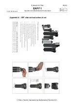
Page 25: ...Hydraulic Oil Filter 25 26 EAPF 1 72 09 195 66 rev B Operation and Maintenance Instructions Parker Hannifin Manufacturing Netherlands Filtration B V Appendix A EPF element instruction sheet ...

Page 26: ......

Reviews: