


Parker Hannifin Corporation
EMN Automation
-
Parker
Irwin, Pennsylvania
29
406LXR Series Product Manual
Chapter 4
-
Performance
Speed Limits
The Maximum Speed of the 406LXR is limited by three
(3)
factors:
1.
Linear Bearings
The linear bearings are limited to a maximum speed of 3 meters/second.
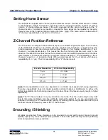
2.
Linear Encoder Limit
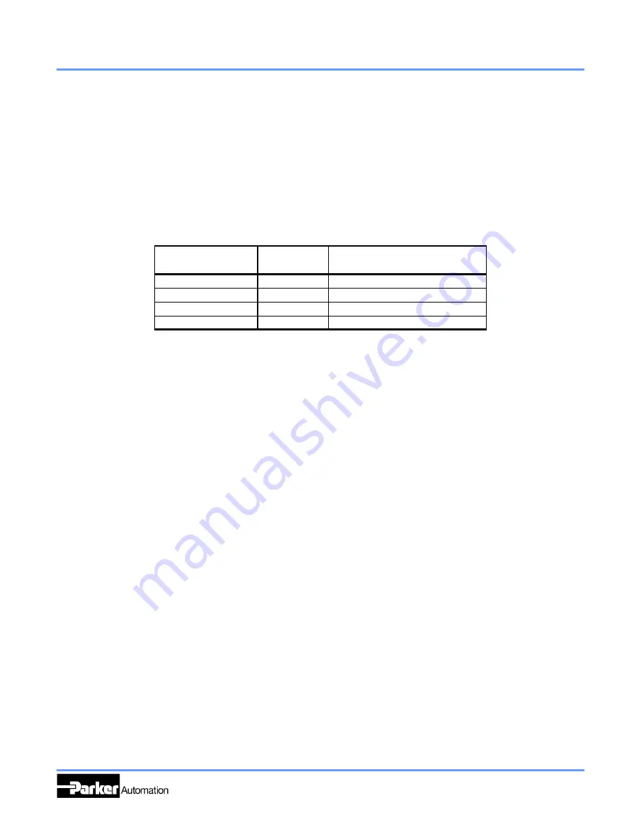
The linear encoder has speed limits relative to encoder resolution; these limits are listed below
Encoder
Resolution
Maximum
Velocity
Required Post Quadrature
Input Bandwidth
2
5 micron
5 m/s
1
2 Mhz
1 micron
3 m/s
6.7 Mhz
0.5 micron
1.5 m/s
6.7 Mhz
0.1 micron
0.3 m/s
10 Mhz
1.
When using an encoder with 5 micron resolution, the maximum speed is limited by the square rail bearings.
2.
This is the bandwidth frequency that the amplifier or servo control input should have to operate properly with the encoder output at
maximum speeds. This frequency is post
-
quadrature, to determine pre
-
quadrature divide above values by 4. Above frequencies include
a safety factor for encoder tolerances and line loses.
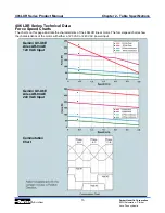
3.
Force / Speed Limit
The available force of the 406LXR reduces as speed increases. (Chapter 2,
406LXR Series Technical
Data
)
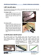
Encoder Accuracy and Slope Correction
Encoder Accuracy
The 406LXR Series makes use of an optical linear encoder for positional feedback. This device
consists of a
readhead
, which is connected to the carriage, and a
steel tape scale
, which is mounted
inside the base of the 406LXR.
The linearity of this scale is +/
-
3 microns per meter, however the absolute accuracy can be many times
larger. To compensate for this error, an error plot of each 406LXR is done at the factory using a laser
interferometer. From this plot a linear slope correction factor is calculated (see below). Then a second
error plot is run using the slope correction factor. These tests are conducted with the Point of
Measurement (P.O.M.) in the center of the carriage 50mm above the carriage surface.
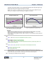
Slope Correction
Slope correction is simply removing the linear error of the table. The graphs below show an example of
a non
-
slope corrected error plot and the same plot with slope correction. As can be seen, the absolute
accuracy has been greatly improved.
The slope factor is marked on each unit. It is the slope of the line in microns per meter. This factor
may be positive or negative, depending on the direction of the error.
If your application requires absolute accuracy, the slope factor must be incorporated into the motion
program. This is a matter of either assigning variables for motion positions and using the slope
Summary of Contents for 406LXR Series
Page 30: ...26 ...
Page 38: ...34 ...
Page 64: ...Parker Hannifin Corporation EMN Automation Parker Irwin Pennsylvania Notes ...
Page 65: ...Parker Hannifin Corporation EMN Automation Parker Irwin Pennsylvania Notes ...
Page 66: ...Parker Hannifin Corporation EMN Automation Parker Irwin Pennsylvania Notes ...
Page 67: ...Parker Hannifin Corporation EMN Automation Parker Irwin Pennsylvania Notes ...
Page 68: ......


