background image

10

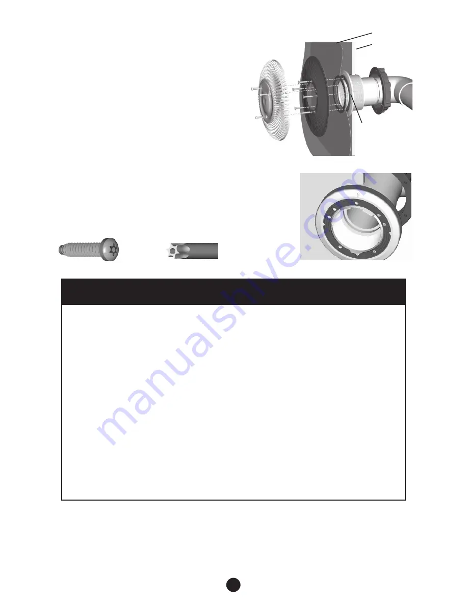
Vinyl Liner

Shell

Notched Gaskets

(Fits One-Way Only)

Fig. 6

Vinyl Cover Assembly (Fig. 4)
1.    Prior to installing the Vinyl Liner, apply adhesive to 

the non-ribbed side of the two notched gaskets.

2.    Align the gaskets with the alignment tabs and screw 

holes, then press the gaskets onto the Bulkhead 
Fitting and the Bulkhead Support.

3.    After installing the Vinyl Liner, align the SDX2 Vinyl 

Fiberglass Support with the alignment tab located at the 
top and bottom of the SDX2 Bulkhead Fitting. (Fig. 5)

4.   Install five (5) self-tapping screws (Fig. 6) through 

the SDX2 Bulkhead Support with the T25 Security 
Screwdriver (Fig. 7). Secure the screws without over 
tightening.

5.    Cut the Vinyl Liner out of the center of the SDX2 

Bulkhead Supports to expose the suction piping.

6.   Align the SDX2 Cover with the SDX2 Support    

holes.

7.    Install three (3) security screws through the SDX2 

cover. Secure the screws without over tightening.

Fig. 4

Fig. 5

WITH CANISTER

If vacuum relief suction outlets are located below freeze line skip steps 1 and 2. 
1.  Remove grate from wall drain and install a 13-¾ blow through plug and blow line to achieve 

airlock.

2.  If 3rd suction line is installed remove grate, install a 13-¾ blow-through plug and blow line 

to achieve airlock.

3.  If vent tube is installed, install blow through plug and blow line to achieve airlock. Repeat 

vacuum out canister. For winterizing canister visit www.1Paramount.com and click on 
winterization instructions.

WITHOUT CANISTER

If vacuum relief suction outlets are located below freeze line skip steps 1 and 2. 
1.  Remove grate from wall drain and install a 13-¾ blow through plug and blow line to achieve 

airlock.

2.  If 3rd suction line is installed remove grate, install a 13-¾ blow-through plug and blow line 

to achieve airlock.

3.  If vent line is installed in main suction line, plug vent line and install blow through plug in 

pump inlet and blow line to achieve airlock.

4. Lastly, blow vent line to achieve airlock.

MDX-R3 WINTERIZATION

Fig. 7

Summary of Contents for MDX-R3

Page 1: ...CIAL INSTRUCTIONS FOR CALIFORNIA ON PAGE 7 Safety compliant according to the Virginia Graeme Baker Pool and Spa Safety Act ANSI APSP 16 2011 Compliant with ANSI APSP 7 2006 WARNING MDX R3 and SDX2 mus...

Page 2: ...perly secured or missing because these conditions increase the chance of death or serious injury from entrapment If a drain cover is discovered damaged cracked broken loose clogged not properly secure...

Page 3: ...ety begins with a professional design that includes a quality suction system installed by a certified contractor Certified builders will address the following issues when designing and installing a pr...

Page 4: ...aining suction outlets serving that system shall have a flow rating capable of the full flow of the pump s for the specific suction system NOTICE MDX R3 VGB COMPLIANT DEBRIS DRAIN STANDARD POOL DESIGN...

Page 5: ...STER AND MV FUSE MV FUSE DECK SIDE SDX2 2ND SUCTION OUTLET 2 1 2 2 1 2 ENLARGED SUCTION ELEMENT IF NOT USING HYDROSTAT PLUG 2 PORT TRUNK LINE MUST BE SIZED TO MEET MAXIMUM VELOCITY REQUIREMENTS FOR SU...

Page 6: ...PER LOCAL CODE TO PUMP TO PUMP TRUNK LINE MUST BE SIZED TO MEET MAXIMUM VELOCITY REQUIREMENTS FOR SUCTION PLUMBING PER LOCAL CODE 2 1 2 OR 3 ENLARGED SUCTION ELEMENT METHOD 2 WITH DECK FUSE IF NOT USI...

Page 7: ...OR SUCTION PLUMBING PER LOCAL CODE TO PUMP EQUAL SIZE AND LENGTH FROM TEE TO EACH DRAIN SDX2 2ND SUCTION OUTLET CALIFORNIA INSTALLATION METHOD 1 WITH CANISTER WITHOUT MV FUSE IF NOT USING HYDROSTAT PL...

Page 8: ...aramount recommends the use of the 2 thread plug provided Do not use check valves here that are prone to sticking open causing the need to open the drain cover exposing a suction risk If a hydrostat i...

Page 9: ...location for the SDX2 drain Additional SDX2 drains may be used 2 For Steel Wall Make one 4 hole using a Greenlee Standard Round Knockout Punch Greenlee com Cat No 742BB UPC No 19978 For Plastic Wall...

Page 10: ...s without over tightening Fig 4 Fig 5 WITH CANISTER If vacuum relief suction outlets are located below freeze line skip steps 1 and 2 1 Remove grate from wall drain and install a 13 blow through plug...

Page 11: ...11...

Page 12: ...ug 4 with O Ring 11 2 Pipe Not Included Cap If Not Used 12 2 Cap Not Included Cap If Not Used 13 005 252 5524 00 Enlarged Suction Element 14 005 252 2550 00 Coupler Reducer 4 X 2 3 005 272 0841 00 Scr...

Reviews: