Paradyne FrameSaver DSL 9783 CSU/DSU Installation Instructions Manual Download Page 20

20

„

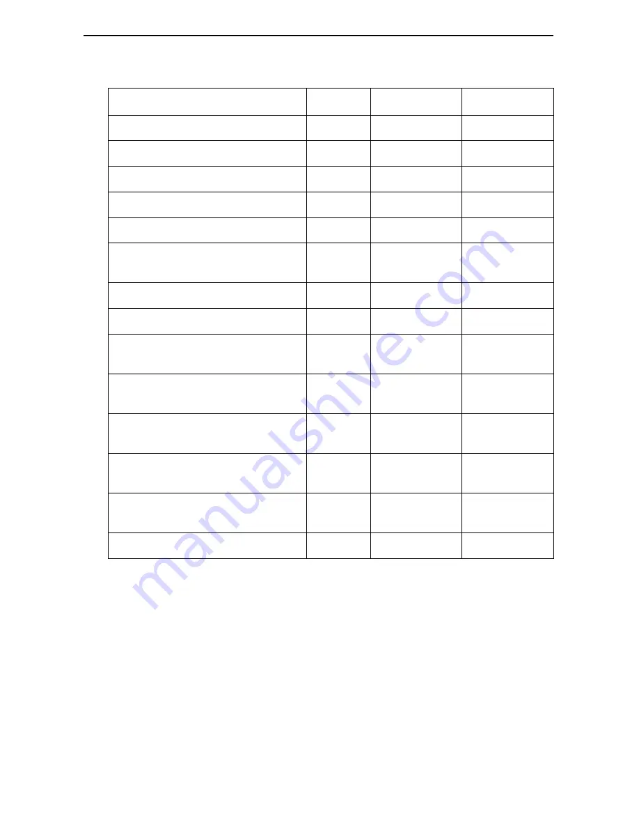
The user data port uses a 34-position V.35 connector that connects to the DTE.

Signal

ITU CT# Direction

34-Pin Socket

Shield

101

A

Signal Ground/Common

102

B

Request to Send (RTS)

105

In (From DTE)

C

Clear to Send (CTS)

106

Out (To DTE)

D

Data Set Ready (DSR)

107

Out

E

Receive Line Signal Detector 
(RLSD or LSD)

109

Out

F

Data Terminal Ready ( DTR)

108/1, /2

In

H

Local Loopback (LL)

141

In

L

Transmit Data ( TXD)

103

In

P (A) and 
S (B)

Receive Data (RXD)

104

Out

R (A) and 
T (B)

Transmit Signal Element Timing – 
DTE Source (XTXC or TT)

113

In

U (A) and 
W (B)

Receive Signal Element Timing – 
DCE Source (RXC)

115

Out

V (A) and 
X (B)

Transmit Signal Element Timing – 
DCE Source (TXC)

114

Out

Y (A) and 
AA (B)

Test Mode Indicator (TM)

142

Out

NN

Summary of Contents for FrameSaver DSL 9783 CSU/DSU

Page 1: ...SU DSU 6 Power On 9 Status LEDs 10 Troubleshooting 11 Configuration Setup 12 Verifying that Self Test Passed 15 Using the Easy Install Screen 15 Completing Setup From the NOC 17 Cables and Connectors...

Page 2: ...the User s Guide for a list of FrameSaver DSL 9783 features and the capabilities provided by each feature set Frame Relay CPE Router FRAD DSL ATM Access Network FrameSaver xDSL Unit 01 16770a Frame Re...

Page 3: ...SLV capability refer to the FrameSaver SLV Activation Instructions Document No 9000 A2 GK43 or contact your sales representative Product Documentation Online Complete documentation for this product i...

Page 4: ...r Paradyne cables contact your sales representative to order them Interface Connection Cables Feature Number COM port to a PC or asynchronous terminal DB25 to DB25 Standard EIA 232 straight through ca...

Page 5: ...ort on the card These custom connections carry the frame relay traffic Note that before the custom cross connects are configured the Maximum VCI number for the uplink VP to be used by these custom con...

Page 6: ...tion Insert one end of the cable into the jack labeled NET Insert the other end into the wall jack for DSL data communications For domestic models go to Step 3 on page 7 2 For certain international mo...

Page 7: ...the cable to an Ethernet hub Do not connect to the hub s optional Uplink connection with a straight through cable the Uplink connection requires an Ethernet crossover cable or Use an Ethernet crossove...

Page 8: ...the EIA 232 cable into the CSU DSU s COM port Tighten the screws on each side of the connector Insert the other end of the cable into the terminal or PC The terminal or PC s configuration must be com...

Page 9: ...SU performs self diagnostics and the PWR LED is on The self diagnostics include a power on self test where all of the LEDs are on Refer to Status LEDs on page 10 for information about the LEDs Refer t...

Page 10: ...Network LEDs ATM ON Green ON Yellow OFF ATM LED is active and cell delineation is in sync ATM mode is active and there is loss of cell delineation The ATM link is not active DSL Blinking ON OFF The C...

Page 11: ...blinking continues for more than ten minutes contact the service provider DSL LED is on but no data is being transmitted The DSL link has been established but there is no data transmission Verify the...

Page 12: ...sioning Typically set up by the CLEC Competitive Local Exchange Carrier using the menu driven user interface via an ASCII terminal or PC running a terminal emulation program or a Telnet session SLM pr...

Page 13: ...et to 19 2 kbps Character Length is set to 8 data bits Parity is set to None Stop Bits is set to 1 Flow Control is set to None 2 Press Enter to display the Main Menu main 9783 C SLV Device Name Node A...

Page 14: ...Menu Configuration Procedure To save configuration changes 1 Press Ctrl a to switch to the function keys area at the bottom of the screen 2 Type s Save and press Enter The Save Configuration To menu...

Page 15: ...rovided for custom configurations but is not required for normal installation You can configure the router by making selections from the Configuration Edit Display menu Procedure 1 Select the Easy Ins...

Page 16: ...able the interface Status Respond Yes to the prompt Would you like to set the Node s Default IP Destination to Ethernet Enter the IP Address and Subnet Mask for the Ethernet interface Enter the Defaul...

Page 17: ...options that require input or changes from default settings Create all customer VCs including internal DLCIs and VPI VCIs on the DSL interface and cross connect the DLCIs to the VCCs Configuring SNMP...

Page 18: ...twire ATM Line Card refer to the Hotwire ATM Line Cards Models 8335 and 8365 User s Guide Document No 8335 A2 GB20 Checking That Data is Being Received Procedure To verify that data is being received...

Page 19: ...data You can also see whether the PVC is active 2 Verify that each PVC is active If active the unit should be passing data If not active no data traffic can be carried by the PVC If the PVC is config...

Page 20: ...dy DSR 107 Out E Receive Line Signal Detector RLSD or LSD 109 Out F Data Terminal Ready DTR 108 1 2 In H Local Loopback LL 141 In L Transmit Data TXD 103 In P A and S B Receive Data RXD 104 Out R A an...

Page 21: ...ons Pin Function 1 10 100BaseT TX D 2 10 100BaseT TX D 3 10 100BaseT RX D 4 5 Not used 6 10 100BaseT RX D 7 8 Not used 98 16055a 8 Pin Plug Ethernet Cable Pin 1 Pin 8 10 100BaseT TX D 10 100BaseT TX D...

Page 22: ...the User s Guide for standard crossover cable external modem pin assignments and AT commands to configure the modem and enable auto answer Pin Signal Direction 1 Shield GND 2 DCE Transmit Data TXD Fr...

Page 23: ...per hour Height x Width x Depth 2 1 x 6 2 x 8 7 5 3 cm x 15 7 cm x 22 1 cm Weight 1 38 lbs 0 62 kg COM Port Standard Data rates 25 position DB25 connector EIA 232 V 24 ISO 2110 9 6 14 4 19 2 28 8 38...

Page 24: ...thorities to ensure compliance 7 A rare phenomenon can create a voltage potential between the earth grounds of two or more buildings If products installed in separate buildings are interconnected the...

Page 25: ...above conditions may not prevent degradation of service in some situations Repairs to certified equipment should be coordinated by a representative designated by the supplier Any repairs or alteratio...

Page 26: ...rules These limits are designed to provide reasonable protection against harmful interference when the equipment is operated in a commercial environment This equipment generates uses and can radiate r...

Page 27: ...utside the U S A call 1 727 530 2340 Document Feedback We welcome your comments and suggestions about this document Please mail them to Technical Publications Paradyne Corporation 8545 126th Ave N Lar...

Page 28: ...9783 A2 GN10 30...

Reviews: