


1823 VoIP Gateway User’s Guide
Chapter 2 Hardware Installation
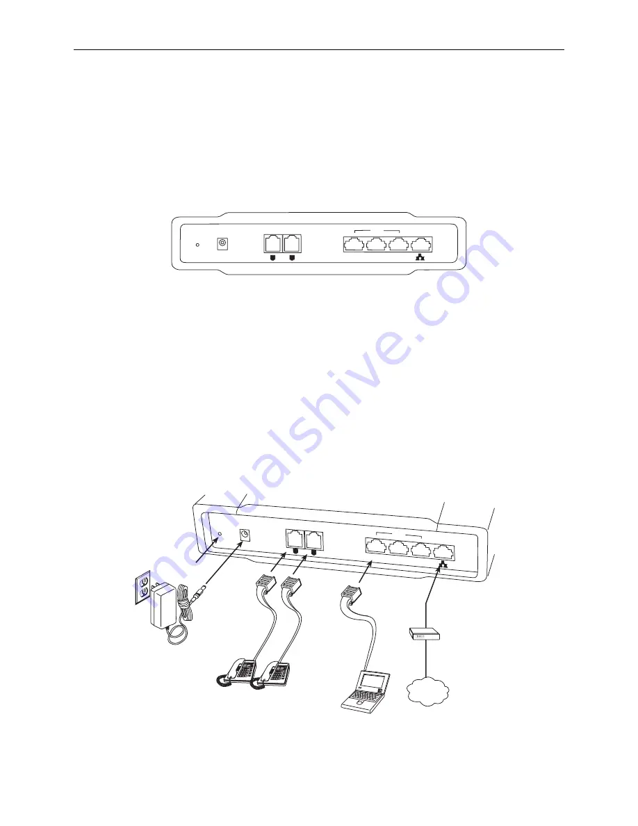
2.1 Back Panel
The figure below illustrates the back panel of the gateway. On the left side of the rear panel there is a
recessed reset button. This button is used to reload the factory default settings. Use a small object like a
ballpoint pen to press the button and hold it down for more than three seconds. The gateway will be reset
and all parameters will return to their factory default settings. You can verify this process by monitoring
the PHONE LED, which will turn off and then on again as the gateway restarts.
05-17660
Power
WAN
LAN
3X
2X
1X
Phone1 Phone2
2.2 Cabling
To install the 1823 VoIP Gateway:
1.
Connect the power adapter to the POWER jack
of the gateway, and then plug the power adapter into
an AC wall outlet.
2.
Use an RJ11 connector cable to connect an analog telephone to the Phone1 port, and, if your service
provider has provisioned two lines, the Phone2 port. An RJ11 cable is supplied with the gateway.
3.
Use RJ45 cables to connect the LAN 1X, 2X, and 3X ports of the gateway to your Ethernet devices,
such as a hub or the Ethernet port of your PC. An RJ45 cable is supplied with the gateway.
4.
Connect the WAN port of the gateway to your ADSL or cable modem’s LAN port with an RJ45 cable.
(If your modem's LAN port is currently connected to your PC, disconnect the cable from the modem's
LAN port and use it to connect your PC to one of the LAN ports of the gateway. Then use another
RJ45 cable to connect the WAN port of the gateway to your modem’s LAN port.)
Power Cable
05-17661
POWER
WAN
Ethernet
Cable
(RJ45)
Telephone
Cable
(RJ11)
Telephone
Device
LAN
3X
2X
1X
PHONE1 PHONE2
Reset
Button
Internet
PC
ADSL / Cable
Modem
LAN Port
If the gateway fails to power on, or it malfunctions, verify that the power supply is correctly connected.
1823-A2-GB20-00 May 2005
9


