Operations Manual, HPA3, Mini Compact Outdoor SSPA
208143 REV -
19
2.2.9 Chassis Ground Pin
A Chassis ground terminal is provided on the bottom side of the amplifier. A ¼ - 20 threaded
terminal is provided for equipment grounding.
2.3 Physical Features
In addition to the I/O connectors, the Mini Compact Outdoor user-friendly features include a
summary alarm indicator and a removable fan tray.
2.3.1 Summary Alarm Indicator
A summary alarm indicator LED is located on the input side of the amplifier. When the SSPA
is online, this indicator illuminates GREEN. When in a fault condition, it illuminates RED.
2.3.2 Removable Fan Tray
The Mini Compact Outdoor Amplifier’s cooling system represents a landmark in microwave
telecommunication amplifiers. It is a unique system of heatsinks that have been computer
optimized to provide extremely efficient cooling of all of the system’s functional blocks. This
high efficiency cooling system is primarily responsible for the small overall package size and
reduced weight of the unit (approximately 24.5 lbs or 11.1 kg).
The cooling system is based on a forced convection technique in which the system fans
provide the air intake while the exhaust is brought out around the outer perimeter of the fans.
The fans are 132 CFM rated and operate into approximately 0.3 in. H
2
O back pressure, and
produce 68.0 dB-A measured at a distance of 1 meter from the fan intake.
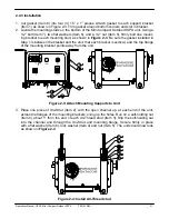
The air intake and exhaust are both located on the bottom side of the amplifier. The intake is
brought through two fans while the exhaust is along the two rows of heatsink fins as seen in
Figure 2-2
.
A minimum clearance of 6 inches (152 mm) should be maintained between the bottom of the
amplifier and any mounting surface. This will ensure that there is no forced re-circulation of
airflow from exhaust to intake.
SWITCH
J6
LINK
J5
RF IN
J1
STATUS
SSPA
ETH
E
RNET READY
M & C
J4
Figure 2-2: Mini Compact Outdoor SSPA Air Flow


