14
208143 REV -
Operations Manual, HPA3, Mini Compact Outdoor SSPA
2.2 Connector Pin-Outs
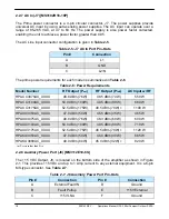
The Mini Compact Outdoor SSPA utilizes a variety of connectors for communication with the
amplifier.
2.2.1 RF In (J1) [Type N (F)]
The RF Input signal is applied to J1, which is a type N female connector. The Mini Compact
Outdoor SSPA has a default maximum nominal gain of 75 dB minimum. Therefore the
maximum input signal required to saturate the amplifier can be calculated as:
Input Power = P
sat
– 75 dB
For example, if a 50 W Ku-Band Mini Compact Outdoor amplifier is used in a system it has a
P
sat
= 47.0 dBm. Therefore the maximum input power should be limited to -28 dBm. Slightly
higher input power levels will not damage the amplifier but will result in higher levels of
distortion in the output signal.
WARNING! The maximum input level should be limited to +15 dBm to
avoid damaging the amplifier.
2.2.2 RF Out (J2)
The amplifier’s output is brought out through the waveguide port, J2. Caution should be
observed here to make sure that the antenna or a suitable termination is connected to this
port before operating the amplifier. The amplifier is protected against full reflection but
dangerous levels of microwave energy can be present at this port.
Ku-Band amplifiers have a WR-75 Grooved Flange while the C-Band and X-Band amplifiers
have CPR style grooved flanges (CPR-137G for C-Band; CPR-112G for X-Band). An isolator
is provided at the output flange with a termination capable of handling full reflected output
power.
WARNING! Never look directly into the RF output waveguide.
Model Number
Weight
Units
HPACC3075AC_XXXX
26.0 (11.8)
lbs. (kg)
HPACC3100AC_XXXX
26.0 (11.8)
lbs. (kg)
HPAXX3050AC_XXXX
25.5 (11.6)
lbs. (kg)
HPAXX3075AC_XXXX
25.5 (11.6)
lbs. (kg)
HPAXX3100AC_XXXX
25.5 (11.6)
lbs. (kg)
HPAXX3175AC_XXXX
25.5 (11.6)
lbs. (kg)
HPAKU3050AC_XXXX
24.5 (11.1)
lbs. (kg)
HPAKU3080AC_XXXX
24.5 (11.1)
lbs. (kg)
Table 2-1: Unit weights (typical)


