V00028CA Rev03
www.panduit.com
Page
16
of
18
45.
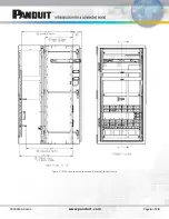
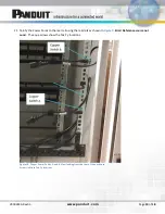
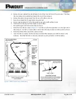
Install a Switch-A switch in RU7 indicated in the equipment elevation (
). Use the mounting angles
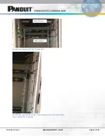
provided with the switch. The horizontal bar on the rear rail (shown in
) will support the switch
eliminating excessive sag.
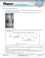
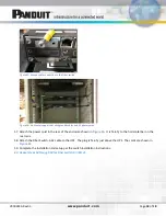
Figure 19: Location of horizontal support bars on rear of IDF.
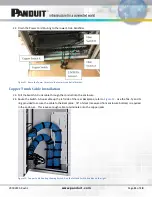
46.
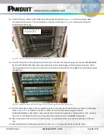
Connect the switch to the patch panel in RUs 5 and 6. Panduit recommends using part number UTP28SP8INBU-
48, Cat6 UTP 28AWG CM/LSZH Cable Assembly, Blue, 8 Inch, Bulk Package of 48 (ordered separately). The 8-
inch length allows for connection from switch port to patch panel without extra length that would require cable
management.
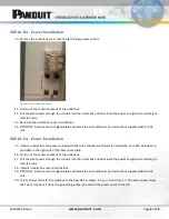
Figure 20: Switch-A (lower) and Switch-B (upper) switches showing fully populated patch cords.
47.
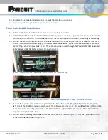
Connect fiber patch cables to the management ports on the right side of the enclosure as shown by the yellow
cable in
. For switches from RU 1 to RU11, Panduit recommends using part number
FX2ERLNLNSNM002,
2-fiber OM3 1.6mm Jacket Patch Cord LSZH LC Duplex to LC Duplex Std IL – 2M
. Connect
the other end of the patch cord to the front side of the FAPs mounted in the FRME1U (step 31a).
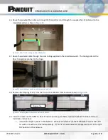
48.
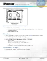
Attach the power cord in the rear of the enclosure. It is labeled and Tak-Ty to the horizontal bar on the rear
rails.
49.
Attach the Switch A and B power cable to the UPS.
shows the location of the AC cords.
Horizontal Support Bars
for Switch A and B

